

User Controls
🍬🍬Candy~Land🍬🍬
-
2024-06-16 at 7:19 AM UTC2 Recommendation T.38 (06/98)
4 Abbreviations
This Recommendation uses the following abbreviations:
ECM Error Correction Mode
IAF Internet Aware Fax device
IFP Internet Facsimile Protocol
IFT Internet Facsimile Transfer
IP Internet Protocol
LSB Least Significant Bit
MSB Most Significant Bit
TCP Transmission Control Protocol
UDP User Datagram Protocol
UDPTL Facsimile UDP Transport Layer protocol
SUB Sub-address
5 Introduction
The availability of IP networks such as the Internet for international communication provides the potential for utilizing
this transmission medium in the transfer of Group 3 facsimile messages between terminals. Since the characteristics of IP
networks differ from those provided by the PSTN or ISDN, some additional provisions need to be standardized to
maintain successful facsimile operation.
The protocol defined in this Recommendation specifies the messages and data exchanged between facsimile gateways
and/or IAFs connected via an IP network. The reference model for this Recommendation is shown in Figure 1.
This model shows a traditional Group 3 facsimile terminal connected to a gateway emitting a facsimile through an IP
network to a receiving gateway which makes a PSTN call to the called Group 3 facsimile equipment. Once the PSTN
calls are established on both ends, the two Group 3 terminals are virtually linked. All standard T.30 session establishment
and capabilities negotiation is carried out between the terminals. TCF is either generated locally or it is transferred
between the terminals, depending on the mode of operation to synchronize modulation rates between the gateways and
G3FEs.
An alternate scenario would be a connection to a facsimile-enabled device (for example, a PC) which is directly
connected to an IP network. In this case, there is a virtual receiving gateway as part of the device’s facsimile-enabling
software and/or hardware. In other environments, the roles could be reversed, or there might be two facsimile-enabled
network devices. The protocol defined by this Recommendation operates directly between the emitting and receiving
gateways. Communication between the gateways and facsimile terminals and/or other devices is outside the scope of this
Recommendation.
The protocol defined in this Recommendation was chosen on the basis of efficiency and economy. For optimum
performance, the IP transmission paths should have reasonably low delays to meet the F.185 requirements. Good image
quality is provided by error control in the network in addition to the means provided by the Recommendation T.30
protocol.
Reliable data transport is provided in two ways: by using TCP over IP networks, or by using UDP over IP networks with
optional means for error control. H.323 systems may utilize either method as described in Annex D/H.323. The H.323
environment is being used to support voice transmission over IP as an alternative to the PSTN. Since facsimile generally
uses the same facilities as voice communications, it may be desirable to utilize the H.323 environment when
implementing facsimile over IP.
Recommendation T.38 (06/98) 3
Heisfksdfjslkjdfiowksdfjkowthiuosd fjksdfsdksdf
sdfksldkfjlsdixcovslkdjfweoijsdvkxcvlkjxk
xcvkosfdjgwoidfvlxcvxocivjosdijfg,dklkdjokjvoisdfkldfg
Heisfksdfjslkjdfiowksdfjkowthiuosd fjksdfsdksdf
sdfksldkfjlsdixcovslkdjfweoijsdvkxcvlkjxk
xcvkosfdjgwoidfvlxcvxocivjosdijfg,dklkdjo kjvoisdfkldfg
T0827880-98/d01
Heisfksdfjslkjdfiowksdfjkowthiuosd fjksdfsdksdf
sdfksldkfjlsdixcovslkdjfweoijs dvkxc vlk jx k
xcvkosfdjgwoidfvlx cvxoc iv josdijfg,dklkdjo kjvois dfk ldfg
PSTN PSTN
Internet-
aware fax
device
Called G3
Facsimile Terminal
Equipment
Receiving
Gateway
Calling G3
Facsimile Terminal
Equipment
IP
NETWORK
Emitting
Gateway
Figure 1/T.38 – Model for facsimile transmission over IP networks
FIGURE 1/T.38...[D01] = CM
4 Recommendation T.38 (06/98)
Under some circumstances it may be necessary to make some adjustments to the procedures between the gateway and the
Group 3 terminal. Any such adjustments should not go beyond those available in the T.30 protocol. These adjustments
are implementation-dependent.
The protocol defined in this Recommendation focuses on the interval where a network connection has been established
between two peers (gateway or IAF) implementing the Real-Time Facsimile document transfer over Internet Protocol.
Management issues, such as directory services (converting PSTN numbers to IP addresses when required), network
hunting, user authentication and CDR (Call Detail Record) collection and network management (SNMP or others) are
important but are not addressed in this Recommendation. Standardization of these issues will allow the implementation of
a network based on third party management devices, including sharing such devices with other Internet gateways such as
Internet telephony and video, remote access and e-mail.
In addition, user interface aspects, such as the way that the facsimile operator selects the PSTN number of the destination
or identifies himself to the system (for security purposes) are also not in the scope of this Recommendation. However, it
is reasonable to assume that the facsimile operator uses the Group 3 terminal equipment keypad (using DTMF signals) or
the IAF keyboard to provide the gateway with the required information.
Some of these issues mentioned here are being addressed in other ITU-T Recommendations. Specifically, Recommen-
dations H.323/H.225 and the Gatekeeper Recommendations address some of the above-mentioned dependencies.
It is intended that all procedures in this Recommendation conform to the requirements of Recommendation F.185.
The main body of this Recommendation describes the protocol and communication procedures between the emitting
gateway and the receiving gateway. Communication between the gateways and the calling and called G3FEs as well as
call control procedures are described in Annex B.
6 Communication between gateways
6.1 Internet protocol – TCP or UDP
The public Internet service provides two principal modes of data transmission:
• TCP (Transmission Control Protocol) – A session-based, confirmed delivery service;
• UDP (User Datagram Protocol) – Datagram service, non-confirmed delivery.
This Recommendation allows the use of either TCP or UDP depending on the service environment. It defines a layered
protocol such that the T.38 messages exchanged for TCP and UDP implementations are identical.
6.2 Gateway facsimile data transfer functions
The emitting gateway shall demodulate the T.30 transmission received from the calling terminal. The T.30 facsimile
control and image data shall be transferred in an octet stream structure using the IFP packets, over a transport protocol
(TCP or UDP). The following signals are not transferred between gateways but are generated or handled locally between
the gateway and the G3FE: CNG, CED, and in one mode, TCF. The gateways may indicate the detection of the tonal
signals CNG and CED so that the other gateway can generate them.
The receiving gateway shall decode the transferred information and establish communication with the called facsimile
terminal using normal T.30 procedures. The receiving gateway shall forward all relevant responses from the called
terminal to the emitting gateway.
The facsimile data transfer structure is described in 7.1.3. The flow between gateways is described in clause 8.
Recommendation T.38 (06/98) 5
6.2.1 Treatment of non-standard facilities requests
The emitting gateway may optionally ignore NSF, NCS and NSS, take appropriate action or pass the information to the
receiving gateway. The receiving gateway may optionally ignore NSF, NCS and NSS or take appropriate action including
passing the information to the receiving G3FE. Information in other frames related directly to these frames may be altered
by the gateway.
7 IFT protocol definition and procedures
7.1 General
This clause contains the textual description of the IFT protocol. The IFT protocol is specified by the ASN.1 description
in Annex A. In the case of a conflict between the ASN.1 and the text, the ASN.1 governs. The ASN.1 encoding in Annex
A should employ the BASIC-ALIGNED version of Packed Encoding Rules (PER) according to Recommendation
X.691.
7.1.1 Bit and octet transmission order
Transmission order is as defined in Internet RFC 791 "Internet Protocol", quoted herein as reference:
– The order of transmission of the header and data described in this document is resolved to the octet level. Whenever
a diagram shows a group of octets, the order of transmission of those octets is the normal order in which they are
read in English. For example, in the following diagram the octets are transmitted in the order they are numbered.
T0828400-98/d02
Figure 2/T.38 – Transmission order of octets (based on RFC 791, Figure 10)
0
0 1 2 3 4 5 6 7 8 9
1
0 1 2 3 4 5 6 7 8 9
2
0 1 2 3 4 5 6 7 8 9
3
0 1
1
5
9
2
6
10
3
7
11
4
8
12
FIGURE 2/T.38...[D02] = CM
– Whenever an octet represents a numeric quantity the left most bit in the diagram is the high order or most significant
bit. This is, the bit labelled 0 is the most significant bit. For example, the following diagram represents the value 170
(decimal).
T0828410-98/d03
Figure 3/T.38 – Significance of bit
(based on RFC 791, Figure 11)
0 1 2 3 4 5 6 7
1 0 1 0 1 0 1 0
FIGURE 3/T.38...[D03] = CM
– Similarly, whenever a multi-octet field represents a numeric quantity the left most bit of the whole field is the most
significant bit. When a multi-octet quantity is transmitted the most significant octet is transmitted first.
6 Recommendation T.38 (06/98)
7.1.2 Mapping of the T.30 bit stream
The T.30 bit stream is mapped so that bit order is maintained between the PSTN and IP networks. This means that the
first bit transmitted is stored in the MSB of the first octet, where the MSB is defined as in 7.1.1.
7.1.3 IFP Packet Layers for TCP/IP and UDP/IP
The IFP packets described in 7.2 are combined with the appropriate headers for TCP/IP and UDP/IP as shown in Figures
4 and 5. In Figure 4, the UDPTL header represents the additional header information required for error control over
UDP.
T0827890-98/d04
IP header IP payload
TCP header TCP payload = IFP packet
IP header TCP header IFP packet
Layered model of
IFP/TCP/IP packet
Flat model of
IFP/TCP/IP protocol
Figure 4/T.38 – High-level IFP/TCP packet structure
FIGURE 4/T.38...[D04] = CM
T0827900-98/d05
IP header IP payload
UDP header UDP payload
UDPTL header UDPTL payload = IFP packet + Redundancy/FEC
IP header UDP header UDPTL header IFP packet + Redundancy/FEC
a) Layered model of
IFP/UDP/IP packet
b) Flat model of
IFP/UDP/IP protocol
Figure 5/T.38 – High-level UDPTL/IP packet structure
FIGURE 5/T.38...[D05] = CM
7.2 IFP packet format
In the following discussion, a message is the protocol or data information transferred in one direction from a G3FE to or
from a gateway during a single period. It may include, for example, one or more HDLC frames, or a "page" of Phase C
data. Messages may be sent across the IP network in multiple packets. The packets may, for example, contain partial or
full, singular or multiple HDLC frames. Support for multiple packets is provided in this protocol. The DATA element
uses Fields to support partial and full HDLC frames.
Recommendation T.38 (06/98) 7
IFP operates (listens) over TCP/IP or UDP/IP using a port determined during call setup. All communication between IFP
Peers is done using packets, identified as IFPPackets.
Table 1 summarizes the IFPPackets (for full explanation, refer to the following subclauses).
Table 1/T.38 – IFP packet elements
7.2.1 T.38 packet
The T.38 packet element provides an alert for the start of a message. It is used by the IFP peer to verify message
alignment. It is identified by an ASN.1 Application tag. When data is read by the peer from its TCP/IP or UDP/IP stack,
and the expected tag is not present, the session should be immediately aborted by the receiver.
7.2.2 TYPE
The TYPE element describes the function of, and optionally, the data of the packet. The legitimate TYPEs are given in
Table 2. Each TYPE is separately explained in the following subclauses. The table also indicates whether the TYPEs are
Mandatory or Optional for implementations using TCP and UDP.
If the TYPE element is not recognized, it and the related data element shall be ignored.
Table 2/T.38 – IFP packet TYPE field
7.2.3 DATA-Field
The DATA-Field element contains the T.30 HDLC control data and the Phase C image (or BFT) data. The structure of
the DATA-Field is defined in 7.4. The structure carries the modulation data as well as indicators for the end of an HDLC
frame, the status of the Frame Check Sequence (FCS) for an HDLC frame, and whether the data represents the end of a
message.
7.3 TYPE definitions
The following subclauses describe the message TYPEs.
7.3.1 T30_INDICATOR
The T30_INDICATOR TYPE is used by the gateways to indicate the detection of signals such as CED, HDLC preamble
flags, and modem modulation training. It is sent by the receiving gateway to the emitting gateway, and by the emitting
gateway to the receiving gateway. The use of this message is optional for TCP implementations and mandatory for UDP
implementations. A peer may send this message in order to notify its peer about upcoming messages. The
T30_INDICATOR TYPE has one of the following values.
Field Description
TYPE Type of message
DATA Dependent on TYPE
Type DATA
Type
Mandatory/
Optional
(TCP)
Mandatory/
Optional
(UDP)
Description
T30_INDICATOR Regular O M Carries indication about the presence of a facsimile
signal (CED/CNG), preamble flags or modulation
indications
T30_ DATA Field M M T.30 HDLC Control and Phase C data (e.g. T.4/
T.6 image segment.)
8 Recommendation T.38 (06/98) -
2024-06-16 at 7:20 AM UTCConsiderations for Using T.38 versus G.711 for Fax over IP
White Paper
Considerations for Using T.38 versus G.711 for Fax over IP2White Paper
Executive Summary
Businesses migrating to Voice over IP (VoIP) often find it desirable to move their fax traffic onto the IP network as well. However,
VoIP networks are, as the name implies, optimized for voice traffic; and businesses implementing a Fax over IP (FoIP) solution as
part of their fax system can benefit from understanding their options for FoIP transport methods.
This white paper compares the performance of the two principal options for sending faxes over an IP network: T.38 fax relay
and G.711 fax pass-through. The V.17 and V.34 modem standards are briefly discussed and also used for comparison when used
with T.38 and G.711 for performance against IP network impairments, such as latency, packet loss, and jitter. The impact of these
network impairments on call control, fax control, and image data are described, as well as the impact of the frequency of these
impairments. General considerations for network performance are also covered, as are sections describing how metrics within
the Dialogic ® Brooktrout ® Bfv API can be used to detect IP network impairments.
Considerations for Using T.38 versus G.711 for Fax over IP3White Paper
Table of Contents
Introduction 4
FoIP Transport Methods 4
T 38 versus G 711 4
V 17 versus V 34 5
Redundancy 5
ECM 5
Typical IP Network Impairments 5
Latency 5
Packet Loss 6
Jitter 6
Impact of Network Impairments 6
Call Control 7
Fax Control 7
Image Data 7
Impairment Frequency 7
Observed Impacts of Network Impairment 7
Effects of Single Packet loss 7
Considerations for Network Performance 13
Dialogic® Brooktrout® SR140 Fax Software 14
Appendix – Detecting Network Issues using Fax Quality Metrics 14
Performance-Improving Features 14
References 18
For More Information 18
Considerations for Using T.38 versus G.711 for Fax over IP4White Paper
Introduction
In the 1990s, “fax” and “T 30” were so entwined that they were basically synonymous T 30, as the ITU recommendation for transmitting faxes
over the general switched telephone network, includes mechanisms to handle background noise and spikes of interference on the telephone
line For example, poor signal quality can be accommodated by lowering the transmission speed, and spikes of noise can be handled by retrying
any operations that are lost during the spike
But T 30 was not designed to deal with IP network impairments such as packet loss, which can result in large gaps in fax data and cannot be
eliminated by a lower transmission speed In fact, lower speeds may actually make the performance worse by generating additional network
traffic that will be exposed to packet loss And retries might not always recover missed data when packet loss is frequent, because the retries can
suffer packet loss as well Even the retry requests themselves may be lost
When upgrading from traditional analog fax to a Fax over IP (FoIP) solution, it is necessary to provide a sufficient level of network performance to
support reliable operation Fax transport over an IP network can be provided by T 38 fax relay and G 711 pass-through, each one having different
network requirements for reliable operation
This white paper describes and compares the T 38 and G 711 fax transport methods for FoIP, using both V 17 and V 34 modem standards, for
performance against typical IP network impairments, such as latency, packet loss, and jitter It then discusses the impact of these network
impairments on call control, fax control, and image data, as well as the impact of the frequency of these impairments This paper also provides
considerations for network performance for each fax transport method, and includes information pertaining to the ways metrics within the
Dialogic ® Brooktrout ® Bfv API can be used to detect IP network impairments
FoIP Transport Methods
When implementing a FoIP solution, the transport method used (T 38 or G 711), in addition to several fax settings such as fax speed, redundancy,
and error correction, can have a significant impact on FoIP performance for common network impairments
T.38 versus G.711
T 38 fax relay is an ITU-T recommendation that allows for fax data to be carried over IP networks Data is transmitted directly in T 38 without being
converted to an audio stream, which results in a significant reduction in the bandwidth needed T 38 also supports data and controls redundancy
to mitigate the effects of packet loss
One disadvantage of T 38 is that gateway support for fax parameters, such as V 34 transmission speed and Error Correction Mode (ECM), is not
universal Also, in the current mixed network environment of packet-based and circuit-switched (that is, PSTN) connections, T 38 often has a
transcoding overhead That can add latency and cost to fax services
G 711 is an ITU-T recommendation for Pulse Code Modulation (PCM) of voice frequencies It uses an uncompressed format and requires high
bandwidth, typically about 64 kbps Using G 711 as the transport method for FoIP is an extension of traditional PSTN audio-based faxing The
digital fax data is converted to a PCM audio stream and then sent as G 711 Real-time Transport Protocol (RTP) packets
G 711 has not been optimized for fax transport over IP networks, and does not typically support packet redundancy Having been developed for
voice, G 711 allows the transmission of missing audio because any gaps would be filled in by a human listener But when used to transmit modem
data, any loss of packets is significant, because the receiver has no way to recreate the missing data
Some packet networks might not be fax-aware, and may optimize the G 711 stream for voice with the use of silence suppression, echo cancellation,
or transcoding to a higher compression codec Such optimizations can cause a loss of data and prevent FoIP from operating This may force
the use of a dedicated G 711 fax trunk to provide reliable fax performance However, G 711 is an inherently simpler approach to fax than T 38, so
interoperability issues between different vendors’ products is less common with G 711 than may be encountered with T 38 The cost for a G 711
approach may also be lower than T 38 because it can leverage voice data infrastructure
Considerations for Using T.38 versus G.711 for Fax over IP5White Paper
V.17 versus V.34
V 17 and V 34 are two commonly used modem specifications for fax that were developed in the PSTN era of faxing, which explains why neither
was designed with IP network impairments in mind V 17 modulation supports bitrates up to 14400 The final transmission speed that is used
is determined during a short training cycle, when a known pattern of bits is transmitted to see if it is received successfully The modem will try
progressively lower speeds until the training pattern is correctly received (known as “training down”) The V 34 specification was introduced
later to achieve higher transmission speeds over traditional PSTN phone lines, and supports bitrates up to 33600 V 34 uses a longer and more
complex training cycle than V 17 to determine the maximum speed the line can support The comparatively higher complexity of V 34 can make
it more vulnerable than V 17 to speed train downs when there are network impairments such as packet loss
Redundancy
Network impairments typically result in lost IP packets Redundancy is a method whereby transmitted information is replicated and repeated in
several packets By repeating data in this way, the probability is higher that, in the end, all of the transmitted information will reach the receiving
side, even if a few packets are lost This can also reduce the need to re-transmit missed information, which in turn may reduce the transmit time
for a fax
T 38 generally supports two types of redundancy:
• Control—Refers to IP packets that contain fax control commands This is sometimes referred to as “low speed” redundancy because in
traditional analog fax, these commands are transmitted at a low data rate of 300 or 1200 bps
• Data—Refers to IP packets that contain fax image data, and is sometimes referred to as “high-speed” redundancy
G 711 can also support redundancy through the use of redundant RTP, but support for this is not currently widespread
ECM
Error Correction Mode (ECM) is a traditional fax check-summing method applied to blocks of fax data Not all fax devices support it, but for
those that do, each segment of fax data is sent with a checksum that is verified by the receiving side If part of the data is corrupted or missing,
the receiving side will request that it be re-transmitted
When ECM is not used, missing data will simply be omitted from the received fax image, causing some degradation in image quality Because
network impairments typically result in the loss of data, ECM can help to preserve image quality in these situations But ECM usage can cause
an increase in both the transmission time and the number of unsuccessful faxes (that is, fax attempts that are not completed) The transmission
time can increase because missing data needs to be requested and re-transmitted The number of unsuccessful faxes can increase because
impairments may corrupt re-transmissions, causing the fax to be aborted when the maximum number of retries is reached
V 34 requires the use of ECM, but with V 17 the use of ECM is optional and often configurable to be on or off
Typical IP Network Impairments
The two most common IP network impairments that impact FoIP are latency and packet loss
Latency
Latency refers to the amount of time it takes transmitted data to reach its destination Round trip latency refers to the amount of time it takes
transmitted data to reach its destination plus the time for the destination’s response to be returned
As IP data is sent from a fax endpoint to a receiving endpoint, the data packets are relayed through a series of network elements The first would
normally be a series of Ethernet routers Then a gateway may receive the data and transcode it into another format For example, a gateway may
transcode a T 38 digital fax into a PSTN audio stream In some cases, the fax may even be routed through more than one gateway
Considerations for Using T.38 versus G.711 for Fax over IP6White Paper
Every network element adds some amount of latency to the data Some add a very small amount on the order of milliseconds, whereas others can
add significantly more time If the data travels over the traditional PSTN network, it may also add delays depending on what type of transmission
devices are used to reach the destination
In general, the amount of latency for a given fax call can vary widely, depending on such factors as the source and destination locations, as well
as what network elements are between them
Packet Loss
Packet loss can occur when network congestion is high and a network element is unable to relay all the packets it receives These congestion
periods may be short lived, such as when a large data file is being transferred on a network This can also occur when high priority data, such as real-
time voice data, is given priority over other network traffic Hardware causes, such as poor signal quality on a cable, can also lead to packet loss
Burst Packet Loss
Burst packet loss refers to a series of consecutive IP packets from a stream not reaching their destination The length of the burst often determines
how negatively it will affect a FoIP call
Single Packet Loss
Single packet loss refers to the occasional loss of single packets (that is, non-consecutive packets) from a data stream This type of loss is not as
significant as burst losses, but can cause serious issues if it occurs frequently
Jitter
Jitter involves elements of both latency and packet loss Jitter refers to variations in latency the network adds to transmitted packets Because
faxes are sent in real time, they require a continuous stream of data to transmit successfully, particularly if the data is being carried as an audio
stream If a packet of data has not been received when it is needed, then the net effect is the same as a lost packet If several packets are received
too late to be used, then that has the same net effect as a burst of lost packets Even if the late packets eventually arrive, it will be too late for the
receiving side to use them, and thus they will be discarded
For FoIP, packet loss due to jitter can be well controlled with the use of jitter buffers This process buffers several packets before they are read
so that the receiver will not run out of packets if some are delayed But a drawback of jitter buffers is that they add latency And when multiple
network elements are in a connection employing jitter buffers, then the latency effect will be additive
Another source of packet loss related to jitter can occur when G 711 faxes experience clock skews This happens when the sender and receiver
are using unsynchronized clock speeds for the audio stream If the sender is creating packets slightly faster than the receiver is reading them,
eventually the jitter buffer of the receiver will overflow and a packet will be lost Or if the receiver is reading packets faster than they are being
sent, eventually the jitter buffer will run dry, and the receiver will not have a packet to read when it needs it
So, although jitter is a form of latency, its impact on fax performance is usually related to how much packet loss it causes, rather than the latency itself
Impact of Network Impairments
Network impairments can cause faxes to fail in many different ways Several layers and phases are employed by FoIP, and each one can react
differently when impacted by network impairment The specific reaction is largely determined by the severity of the impairment and which
phase of the call is in progress when the impairment happens On an application level, fatal errors will typically be reported by the fax API
function that was in progress when the impairment occurred Non-fatal errors are not reported by all types of network elements, but can be
observed by products that support the collection of network quality metrics, such as those in the Dialogic ® Brooktrout ® Bfv API, the application
programming interface used for developing fax solutions based on both the Brooktrout Dialogic ® Brooktrout ® SR140 Fax Software and the
Dialogic ® Brooktrout ® Fax Boards (see “Detecting Network Issues using Fax Quality Metrics” in the Appendix below)
Considerations for Using T.38 versus G.711 for Fax over IP7White Paper
Call Control
The first phase of a fax that can be impacted by network impairments is the call control phase For FoIP, call connections are generally controlled
with the Session Initiation Protocol (SIP) or H 323 protocols For example, if packets are lost on the network and the call setup packet is dropped,
then the receiving side will not know that a call request has occurred The sender will wait for a response, eventually time out, and end with a “no
answer” or “line busy” error If the response packet to the call setup is dropped, the result would be similar To complete the call, the fax server
or user would need to make another attempt to send the fax
Other call control operations that can be impacted include the fax transport negotiations (that is, setting up T 38 or G 711) and call termination
Fax Control
Once a call has successfully transitioned into fax mode, using either T 38 or G 711, the call enters the fax control phase During this time, traditional
T 30 fax operations take place, such as training the modem to the highest working bitrate, and negotiating to send the next page in the fax Packet
loss during this time could cause the fax speed to train to a lower speed, or cause the fax to fail altogether Lower speeds will increase the fax
transmission time
If fax control commands or their acknowledgements are dropped, it triggers multiple retries (usually up to three) for those commands until they
succeed, or until one side gives up and ends the call The result could be that all or just part of the fax is truncated at the receiving end
High latency may cause fax control failures because T 30 has required timer values for completing some command sequences For example, most
commands use a three second timer for receiving a response If a response is excessively delayed, these timers will be exceeded and the call will
fail Fax calls that end prematurely will need to be re-sent by the fax server or a user
Image Data
During the fax data phase, the actual image data for each fax page is transmitted Depending on whether ECM is being used, missed data will
be re-requested or simply left out of the received image If re-requested, the fax transmission time will increase If packets for the re-transmission
requests are lost, then there will be further delays and possibly failure of the fax if retry limits are reached If ECM is not used, then lost data will
result in omissions in the received fax image, usually in the form of missing or repeated horizontal strips
Impairment Frequency
How often the network impairment occurs can also have a large impact on the overall fax completion rate If the impairment is continuous, (for
example, consistently dropping some percentage of transmitted packets) then the impact on the fax completion rate will be more pronounced
Also, with a continuous impairment, faxes with longer durations (that is, those faxes with a large number of pages) will have a greater exposure to
the impairment, thus increasing the chance the fax will fail or terminate prematurely
If the impairment is infrequent and short in duration, it will have less of an overall impact on fax performance However, it is important to note
that some packets within a fax transmission are more critical and vulnerable to loss than others Data packets, for example, can often be lost
without causing the fax call to fail, but the loss of certain control packets can more readily lead to a failed call With that in mind, even a small and
infrequent network issue could result in occasional fax failures, if, by chance, it impacts a particularly important set of packets
Observed Impacts of Network Impairment
Figures 1 through 12 are test examples showing the effect of network impairments on different FoIP transport configurations For these tests,
two servers, each equipped with a FoIP test application created using Brooktrout SR140, were connected using an artificially impaired network:
Brooktrout SR140 ↔ Artificially impaired IP network ↔ Brooktrout SR140
Effects of Single Packet loss
As a general consideration, Table 1 shows the levels of single packet loss that can be observed on various types of networks [ITU-T]
Considerations for Using T.38 versus G.711 for Fax over IP8White Paper
Network Type Single Packet Loss
Well managed IP network (that is, supports real-time applications with strict constraints) < 0 05%
Partially managed IP network < 2%
Unmanaged IP network (Internet) < 20%
Table 1. Single Packet Loss on Various Network Types -
2024-06-16 at 7:21 AM UTCA T.38 gateway is really just the modem section to take FAX analog "audio" data on the phone line and turns it a straight binary digital packet stream of lower level T.30 HDLC data. The T.38 standard does specify some level of application level decoding to extend the timers in certain FAX acknolwedgement handshakes....in effect the T.38 gateway buys some time at his end with the FAX machine at the other end of the phone call while stuff makes it through the IP network...especially if there is packet loss etc. However, all of that is going on between the T.38 gateway and the FAX machine....not towards the IP network.
So, if you really want to peer into the IP packet end of the T.38 gateway and actually want to get access to the FAX'ed document images and render that as TIFF, what you really are looking for is T.30 FAX Termination since T.30 specifies the format of the HDLC data and how to encode/decode that content. In effect, you have to implement the FAX machine's logic to capture the documents into TIFF in the same way that a real FAX machine would have captured the images and printed to paper.
ie: What you are really for is a T.30 implementation, not a T.38 implementation. Note that part of the the T.30 standard also references T.4 which describes how the the actual image data is compressed within the context of T.30.
Relative to going from T.38 to T.37, while I suppose that would be theoretically possible, understand that just like T.38, the T.37 standard assumes that one end of such a gateway is the analog domain. That is, the standard of T.37 specifies how to go from analog to an email message in the same way that T.38 goes from analog to real-time digital packet stream. In the context of the standards there is no "double hop" from T.38 to T.37 to get to your FAX images....so I think finding an existing implementation seems unlikely.
In the end, what you need is a T.30 FAX termination implementation since the T.38 gateway you are talking to is already doing the modem part for you. Alternatively, another way of looking at this is that you want a T.37 gateway instead of a T.38 gateway.
Asterisk the open source PBX uses the SpanDSP library to implement faxing. It looks like that library has modules to handle T.38 and the other protocols InSciTek Jeff mentioned.
OPAL is a library that supports T.38 (Only up to 14400) (It can also use spandsp to deal with G711 audio containing fax tones). Commercial options also exist, mostly from Dialogic and Commetrex. -
2024-06-16 at 7:21 AM UTC

*tokez*
*strums guitar* -
2024-06-16 at 7:25 AM UTCV.34 Fax Relay over Packet Networks
December 2011
WHITE PAPER
Table of Contents
Scope 3
Standard Abbreviations 3
Overview 3
Phase E – Call release 7
V.34 Fax Relay Stimulus Signals 7
Calling Fax Tone (CNG) 7
V.8 Answer Tone (ANSam) 7
CNG and Answer Tone 7
V.8 CM 8
V.21 Preamble Flags 8
V.34 Fax Relay in Fallback Mode 8
V.34 Fax Relay per T.38 Version 3 9
T.38 Call Setup 10
Why Choose AudioCodes? 11
References 12
V.34 Fax Relay over Packet Networks
WHITE PAPER
2
Scope
This white paper provides a technical overview of V.34 fax technology and is intended for Fax over IP (FoIP)
application and test engineers, FoIP gateway vendors and customers, and FoIP customer support. A brief
introduction in V.34 fax relay technology is given with reviewing fax signals exchanged during different phases
of V.34 fax call, stimulus signals for transitioning gateways to V.34 fax relay, different methods of V.34 fax
communication over the Internet, and optimal methods of T.38 call establishment.
Standard Abbreviations
ANSam V.8 Answer tone, 2100 Hz, amplitude‐modulated
CI V.8 Call Indicator signal
CJ V.8 CM terminator
CM V.8 Call Menu signal
JM V.8 Joint Menu signal
CFR T.30 Confirmation to Receive
CNG T.30 Calling fax tone
CSI T.30 Called Subscriber Identification
DCN T.30 Disconnect
DCS T.30 Digital Command Signal
DIS T.30 Digital Identification Signal
EOP T.30 End of Page
ECM T.30 Error‐Correction Mode
HDLC High‐level Data Link Control
MCF T.30 Message Confirmation
PPS T.30 Partial Page Signal
SDP Session Description Protocol
SIP Session Initiation Protocol
TCF T.30 Training Check Frame
TSI T.30 Transmitting Subscriber Identification
Overview
The late 1990s and early 2000s were remarkable for the appearance and widespread proliferation of high‐
speed faxes based on the V.34 half‐duplex modulation system. Faxes featuring V.34 modulation capability are
also known as “super G3” faxes. Relative to regular G3 faxes, V.34 faxes significantly reduce the total time of
fax image transfer over PSTN. The time saving is achieved thanks to the following V.34 advantages:
• Fax image transfer at higher data rates of up to 33600 bps vs. the regular G3 maximum fax rate of
14400 bps
• Estimation of optimal symbol rate, data signaling rate and other modulation parameters while
avoiding using T.30 TCF
• Capability of fast renegotiation of the data signaling rate without restarting T.30 Phase B
• Fast T.30 control at 1200 bps full‐duplex vs. 300 bps half‐duplex V.21 of regular G3 faxes
The T.38 Recommendation initially published in 1998 defined the regular T.30 fax relay over IP (FoIP). Due to
high complexity of V.34 modulation, and due to the T.30 incompatibility of V.34 fax relative to regular fax
communication, for several years the T.38 had no support of V.34 fax relay; and the first three versions of T.38
– namely, version 0 (dated 1998), version 1 (dated 2000), and version 2 (dated 2002) – were based on regular
fax modulation schemes.
Two alternative methods of transferring V.34 fax calls over packet networks were used and continue to be
used today:
V.34 Fax Relay over Packet Networks
• Voice‐Band Data (VBD) fax transfer per V.151.1 and V.152
WHITE PAPER
• V.34 fax fallback to regular G3 fax relay at data rates of up to 14400 bps (V.17 modulation)
In VBD mode, all V.34 fax signals are transferred using a low distortion compression, for example, PCM A‐/‐μ
laws. The VBD method is attractive because it is least complex compared to FoIP and it allows a native V.34
operation at fax rates of up to 33600 bps. But VBD transfer may be problematic because:
3
• The VBD stream cannot be used by fax servers, internet‐aware faxes, and other fax relay oriented
applications
• Broad bandwidth consumption even without redundancy (≈64 kbps, full‐duplex)
• Low immunity to packet loss
• Low tolerance to network jitter and constant delay
• Low tolerance to sampling rate difference (or clock offset) between originate and answer side
gateways
• High sensitivity to imperfections of echo canceling
In order to allow FoIP communication between V.34 fax terminals by using T.38 of version 0, version 1 or
version 2, a FoIP gateway may need to force the V.34 fax terminals to operate in a fallback mode limited by
V.17 modulation at data signaling rates (fax rates) of up to 14,400 bps. Gateways may use different methods
to force a V.34‐to‐V.17 fallback which result in establishing a T.38 session based on regular (non‐V.34)
modulation at both sides of communication.
A growing usage of V.34 fax terminals required adequate signal processing by FoIP gateways and an adaptation
of the FoIP protocol. Accordingly, version 3 of the T.38 (dated 2007) defines an extended FoIP protocol of V.34
fax communication over IP at fax rates of up to 33,600 bps.
The following sections summarize important T.30 definitions for full V.34 fax relay and V.34 fax relay in fallback
mode.
V.34 Fax Call over the PSTN
A V.34 fax call may be divided into the following phases (according to ITU‐T recommendations T.30 from
09/2005 and V.34 from 02/98):
• Phase A – V.34 Call Establishment
• V.34 Phase 2 – Line probing
• V.34 Phase 3 – Primary channel equalizer training
• Phase B – Pre‐message procedures
• Phase C – In‐message procedure
• Phase D – Post‐message procedure
• Phase E – Call release
Figure 1 and Figure 2 show an example of a single fax call (Phase A through to D).
T.30 Phase A – V.34 Call Establishment
Figure 1 shows a typical signal flow corresponding to T.30 Phase A of V.34 call establishment.
Phase A starts with a tonal exchange between calling and answering fax terminals. It includes V.34 Phase 1
beginning with an ANSam tone. During V.34 Phase 1, the fax terminals exchange V.8 CM and JM messages to
define the fax call type. If the answering fax does not confirm having V.34 fax capability, then when the V.8
signal exchange is complete, the fax terminals enter regular T.30 Phase B. If the answering fax confirms V.34
capability, the terminals enter proper V.34 fax procedures, shown in Figure 2.
Generally, a more complex scenario is possible when an answering fax terminal uses regular T.30 Phase B for
transmission of T.30 capabilities (DIS) before it enters normal V.34 operation. In this case, the calling fax may
transmit the V.8 CI signal to initiate V.34 Phase 1.
V.34 Fax Relay over Packet Networks
WHITE PAPER
4
Figure 1: T.30 Phase A – V.34 Call Establishment
V.34 Phase 2 – Line Probing
Entering V.34 Phase 2, fax terminals send full‐duplex INFO0c and INFO0a signals at 600 bps to exchange the
supported symbol rates and other V.34 capabilities. After a successful exchange by INFO0 sequences, the
originating fax modem transmits line probing signals. The answering fax modem receiving the line probing
signals analyzes the channel characteristics and selects the optimal symbol rate, carrier frequency, pre‐
emphasis enhancement, and power reduction to be used during V.34 Phase 3 and later for every fax page of T.30 Phase
C. The selected parameters and requested V.34 TRN duration are forwarded to the originating fax by INFOh
sequence. After successfully transferring INFOh, the originating and answering modems enter V.34 Phase 3.
V.34 Phase 3 – Primary Channel Equalizer Training
In this phase, the originating fax modem sends a half‐duplex TRN signal. An answering fax modem receiving
the TRN trains the primary channel equalizer and precoder coefficients and adapts the other demodulation
parameters. When TRN duration expires, the fax modems launch a V.34 control channel (1200 bps, full‐duplex)
and exchange modulation parameter sequences: The MPh0 sequence of the originating modem and the MPh1
sequence of the answering modem. The MPh modulation parameters contain a maximum data signaling rate
and other options offered by the V.34 modem. The MPh1 sequence sent by the answering fax additionally
includes the precoder coefficients which should be used by the primary channel transmitter of the originating
fax.
After a successful exchange of modulation parameters, the fax terminals continue the full‐duplex operation of
the control channel and enter T.30 Phase B with transmission of HDLC flags.
V.34 Fax Relay over Packet Networks
WHITE PAPER
5
Figure 2: V.34 Fax Procedures
Phase B – Pre‐Message Procedures
After Phase B, all pre‐ and post‐message commands and responses of T.30 control are exchanged using the
V.34 control channel. The content of T.30 frames exchanged using the V.34 control channel is similar to that of
a regular G3 fax session. But the process is much faster relative to regular T.30 control exchange by V.21,
because
• The V.34 control channel bit rate is 4 times faster
• HDLC preamble of duration 1.0±0.15 sec is not required. According to T.30, at least two HDLC
flags (13.3 msec) are enough to send before the first HDLC frame.
The V.34 fax modulation system does not use TCF defined by T.30 for Phase B of regular G3 fax. In Phase B (see
Figure 2), an answering V.34 fax sends T.30 capabilities [CSI/] DIS to the originating fax and waits for a DCS
command. On receipt of the DIS from the answering fax, the originating V.34 fax sends a [TSI/] DCS command
and waits for CFR confirmation. On receipt of the DCS from the originating fax, the answering fax responds
with a CFR. The originating fax, on receipt of the CFR, starts a normal turn‐off procedure of the control channel
after which both faxes enter T.30 Phase C of fax image transfer.
By analyzing the telephone line for maximum use of line bandwidth and estimating modulation parameters
required for optimum image transfer, the V.34 faxes substantially reduce a total duration of phases preceding
Phase C relative to regular G3 fax. The highest gain in transmission time preceding T.30 Phase C is achieved
when line conditions do not allow transferring a G3 fax at the maximum data rate. Where a regular G3 fax may
perform some attempts in Phase B to choose an appropriate data rate and modulation system (V.17, V.29, or
V.27), a V.34 fax is capable of entering the image transfer directly after a single attempt of line probing and
TRN.
Phase C – In‐Message Procedure
The binary data of fax image and Return‐to‐Control for Partial page (RCP) frames are sent using the half‐duplex
primary channel. T.30 Error‐Correction Mode (ECM) is mandatory for V.34 faxes.
V.34 Fax Relay over Packet Networks
WHITE PAPER
The primary channel signal is transmitted using a symbol rate, carrier frequency, pre‐emphasis enhancement, and
power reduction specified by INFOh from the answering fax. The data signaling rate is the maximum rate
enabled that is less than or equal to the data signaling rates specified in both modems’ MPh sequences. The
other modulation parameters of primary channel (types of trellis and non‐linear encoders, constellation
6
shaping, and precoder enhancement coefficients) are applied according to the values specified by MPh1 of the
answering fax modem.
After transmission of the fax image and RCP, the originating fax turns off the half‐duplex primary channel and
enters T.30 Phase D.
Phase D – Post‐Message Procedure
In Phase D, the communicating modems resynchronize the V.34 control channel. Also, instead of
resynchronization of the control channel, a fax modem may initiate a control channel start‐up followed by
modulation parameters MPh exchange. This is useful when a change of MPh is required. For example, an
answering fax that received a fax image of Phase C as non‐satisfactory, may request a reduction of the data
signaling rate. In contrast to regular G3 fax procedures, renegotiation of the data rate is extremely fast and
does not require retraining the image type modulation system.
After resynchronization of V.34 control channel or control channel start‐up with MPh renegotiation, the
modems are ready to exchange a T.30 post‐message command of the originating fax, for example, PPS‐EOP,
and post‐message response of the answering fax. If a final partial page is positively confirmed by MCF of the
answering fax, the originating fax sends a DCN (see Figure 2).
On completion of Phase D, fax terminals execute a normal turn‐off procedure of the control channel. If the fax
image transfer is not completed, or a retransmission is required, then the fax terminals return to Phase C. In
case of DCN exchanged, the fax modems terminate the fax session via T.30 Phase E.
Phase E – Call release
Fax terminals physically disconnect. Under certain conditions, call release may be irregular, for example,
before completion of image transfer.
V.34 Fax Relay Stimulus Signals
Calling Fax Tone (CNG)
A calling fax tone (CNG) is common to regular G3 and V.34 fax calls. Generally, the CNG stimulus tone provides
transitioning to fax relay with highest reliability because gateways may switch a voice‐over‐IP (VoIP) operation
mode onto a fax relay during a silence period of CNG. Sometimes, however, fax relay initiated by a CNG tone
may be undesirable, for example, if:
• Call progress and/or speech signals exist during CNG
• Called terminal equipment is a regular telephone and not a fax
According to V.150.1, the CNG alone is not enough to indicate that a call is a facsimile and in some cases, the
originating fax may not transmit it.
V.8 Answer Tone (ANSam)
As stimulus signals, a called fax tone CED and a V.8 answer tone ANSam allow safe transitioning of gateways
from VoIP or VBD to fax relay state. To avoid answer tone irregularities caused by the gateway switching from
VoIP to a non‐VoIP state, ITU‐T V.150.1 recommends blocking the answer tone sent from the answering
equipment in the direction of the network, while the gateway determines answer tone type.
As the ANSam signal is common to V.34 fax and modem terminals, using only ANSam as a stimulus of V.34 fax
relay may be problematic for modem transport over packet networks, though in environments without
modems or in fax server gateways, the ANSam may be a recommended stimulus signal for transitions to V.34
fax relay.
V.34 Fax Relay over Packet Networks
WHITE PAPER
CNG and Answer Tone
AudioCodes gateways performing bi‐directional monitoring of fax signals use the following signal combinations
as stimuli for safest transitioning to fax relay:
7
• A CNG detected from the network and an answer tone received from TDM input
• A CNG received from TDM input and an answer tone detected from the network
Out‐of‐band signaling may be applied as an alternative to monitoring the signals decoded from the network
stream.
V.8 CM
A V.8 call menu (CM) sent by a calling fax terminal in response to an ANSam received from an answering fax
terminal is definitely a good signal for discriminating V.34 fax calls. But for fax relay call setup, the V.8 CM may
be less safe compared to CNG and/or ANSam because transition to fax relay state occurs in the middle of the
answer tone and may cause tone irregularities. AudioCodes gateways use the V.8 CM stimulus signal if they’re
not switched to fax relay at earlier stages.
V.21 Preamble Flags
The V.21 preamble of HDLC flags is common to regular G3 fax and manual V.34 fax calls. It is a good signal for
fax call discrimination and is considered a mandatory stimulus for transitioning to fax relay. Sometimes,
though, a switch to fax relay ‐ initiated by V.21 preamble flags ‐ may be problematic due to:
• Irregularities in the V.21 signal caused by the switch
• Prolonged gateway negotiation at stage of T.38 call setup, possibly resulting in loss or irregular
delay of T.30 data
AudioCodes gateways use the V.21 preamble as a final stimulus signal if they’re not switched to fax relay at
earlier stages.
V.34 Fax Relay in Fallback Mode
When a V.34 capable fax terminal (super G3) communicates with a regular G3 fax, the fax call is always regular
G3:
• A calling V.34 fax terminal cannot start in V.34 Phase 1 because the answering G3 fax terminal
cannot transmit an ANSam
• An answering V.34 fax enters regular Phase B after an ANSam because the calling G3 fax terminal
cannot transmit a V.8 CM.
For such calls, independently of T.38 version capabilities of communicating gateways, the corresponding fax
relay session will be regular G3 fax relay performed at fax data rates up to 14400 bps of V.17. The only non‐
regular T.38 packet v8‐ansam may appear at the beginning of fax relay session if both gateways support T.38
version 3.
A more complex scenario takes place when V.34 fax terminals connect through gateways not supporting V.34
fax procedures. For example, if ANSam and V.8 CM signals are transferred in VoIP or VBD mode, then gateways
waiting for the V.21 preamble may miss the possibility of entering fax relay because V.34 faxes do not use
HDLC protocol during automatic V.8 negotiation.
To resolve this problem, according to T.38 Recommendation, gateways not supporting T.38 version 3 must
prevent transferring the fax CM over VoIP or VBD to the answering fax terminals, and avoid V.8 capability to be
relayed in V.21 DIS frame to calling fax terminals.
Some gateways may support T.38 version 3 or higher but not be capable to V.34 modulation system, for
example, gateways may use high versions of T.38 to allow obsolete V.33 modulation (14400/12000 bps)
or/and new methods of T.38 call establishment. Such gateways, alternatively to blocking V.8 interaction, may
allow T.38 v8‐cm‐message/v8‐jm‐message packet exchange, but prevent the relaying V.34 modulation
capability.
V.34 Fax Relay over Packet Networks
WHITE PAPER
After avoiding or resolving the V.8 negotiation problem, the gateways may continue regular fax relay which
forces V.34 fax terminals to operate in non‐V.34 mode at fax data rates of up to 14400 bps of V.17.
8
V.34 Fax Relay per T.38 Version 3
The following Figure 3 is a schematic block‐diagram illustration of a FoIP communication system. System may
include, on one communication side, a calling or answering V.34 fax terminal connected to a switched
network, and may further include, on another communication side, an IP network connected to a remote
gateway or an IP fax device. A FoIP gateway may be connected between the switched network and the IP
network. The remote FoIP capable gateway, in turn, may be connected to a fax terminal, which may be an
answering or calling fax terminal.
Figure 3: Typical layout of V.34 FoIP communication
A FoIP gateway may receive analog signals from a facsimile terminal, for example the V.34 fax terminal,
through the switched network. The FoIP gateway may demodulate or convert the analog fax transmission to a
fax data set, may encode and packetize the fax data set according to the T.38 FoIP protocol, and may relay the
fax packets over the IP network to the remote gateway or to an Internet‐aware fax device, e.g., the IP fax.
Independently of whether a V.34 fax relay call is initiated during automatic or manual T.30 call establishment
procedures, the local and remote gateways must finally pass V.34 Phase 1 of V.8 ANSam/CM/JM interaction to
enter the main V.34 fax signal processing. A V.34 FoIP gateway receiving a V.34 CM signal from a connected
V.34 call fax may send a T.38 v8‐cm‐message packet carrying a T.38 Facsimile Application Profile (FAP). As a
response on the v8‐cm‐ -
2024-06-16 at 2:12 PM UTC
Originally posted by the man who put it in my hood V.34 Fax Relay over Packet Networks
December 2011
WHITE PAPER
Table of Contents
Scope 3
Standard Abbreviations 3
Overview 3
Phase E – Call release 7
V.34 Fax Relay Stimulus Signals 7
Calling Fax Tone (CNG) 7
V.8 Answer Tone (ANSam) 7
CNG and Answer Tone 7
V.8 CM 8
V.21 Preamble Flags 8
V.34 Fax Relay in Fallback Mode 8
V.34 Fax Relay per T.38 Version 3 9
T.38 Call Setup 10
Why Choose AudioCodes? 11
References 12
V.34 Fax Relay over Packet Networks
WHITE PAPER
2
Scope
This white paper provides a technical overview of V.34 fax technology and is intended for Fax over IP (FoIP)
application and test engineers, FoIP gateway vendors and customers, and FoIP customer support. A brief
introduction in V.34 fax relay technology is given with reviewing fax signals exchanged during different phases
of V.34 fax call, stimulus signals for transitioning gateways to V.34 fax relay, different methods of V.34 fax
communication over the Internet, and optimal methods of T.38 call establishment.
Standard Abbreviations
ANSam V.8 Answer tone, 2100 Hz, amplitude‐modulated
CI V.8 Call Indicator signal
CJ V.8 CM terminator
CM V.8 Call Menu signal
JM V.8 Joint Menu signal
CFR T.30 Confirmation to Receive
CNG T.30 Calling fax tone
CSI T.30 Called Subscriber Identification
DCN T.30 Disconnect
DCS T.30 Digital Command Signal
DIS T.30 Digital Identification Signal
EOP T.30 End of Page
ECM T.30 Error‐Correction Mode
HDLC High‐level Data Link Control
MCF T.30 Message Confirmation
PPS T.30 Partial Page Signal
SDP Session Description Protocol
SIP Session Initiation Protocol
TCF T.30 Training Check Frame
TSI T.30 Transmitting Subscriber Identification
Overview
The late 1990s and early 2000s were remarkable for the appearance and widespread proliferation of high‐
speed faxes based on the V.34 half‐duplex modulation system. Faxes featuring V.34 modulation capability are
also known as “super G3” faxes. Relative to regular G3 faxes, V.34 faxes significantly reduce the total time of
fax image transfer over PSTN. The time saving is achieved thanks to the following V.34 advantages:
• Fax image transfer at higher data rates of up to 33600 bps vs. the regular G3 maximum fax rate of
14400 bps
• Estimation of optimal symbol rate, data signaling rate and other modulation parameters while
avoiding using T.30 TCF
• Capability of fast renegotiation of the data signaling rate without restarting T.30 Phase B
• Fast T.30 control at 1200 bps full‐duplex vs. 300 bps half‐duplex V.21 of regular G3 faxes
The T.38 Recommendation initially published in 1998 defined the regular T.30 fax relay over IP (FoIP). Due to
high complexity of V.34 modulation, and due to the T.30 incompatibility of V.34 fax relative to regular fax
communication, for several years the T.38 had no support of V.34 fax relay; and the first three versions of T.38
– namely, version 0 (dated 1998), version 1 (dated 2000), and version 2 (dated 2002) – were based on regular
fax modulation schemes.
Two alternative methods of transferring V.34 fax calls over packet networks were used and continue to be
used today:
V.34 Fax Relay over Packet Networks
• Voice‐Band Data (VBD) fax transfer per V.151.1 and V.152
WHITE PAPER
• V.34 fax fallback to regular G3 fax relay at data rates of up to 14400 bps (V.17 modulation)
In VBD mode, all V.34 fax signals are transferred using a low distortion compression, for example, PCM A‐/‐μ
laws. The VBD method is attractive because it is least complex compared to FoIP and it allows a native V.34
operation at fax rates of up to 33600 bps. But VBD transfer may be problematic because:
3
• The VBD stream cannot be used by fax servers, internet‐aware faxes, and other fax relay oriented
applications
• Broad bandwidth consumption even without redundancy (≈64 kbps, full‐duplex)
• Low immunity to packet loss
• Low tolerance to network jitter and constant delay
• Low tolerance to sampling rate difference (or clock offset) between originate and answer side
gateways
• High sensitivity to imperfections of echo canceling
In order to allow FoIP communication between V.34 fax terminals by using T.38 of version 0, version 1 or
version 2, a FoIP gateway may need to force the V.34 fax terminals to operate in a fallback mode limited by
V.17 modulation at data signaling rates (fax rates) of up to 14,400 bps. Gateways may use different methods
to force a V.34‐to‐V.17 fallback which result in establishing a T.38 session based on regular (non‐V.34)
modulation at both sides of communication.
A growing usage of V.34 fax terminals required adequate signal processing by FoIP gateways and an adaptation
of the FoIP protocol. Accordingly, version 3 of the T.38 (dated 2007) defines an extended FoIP protocol of V.34
fax communication over IP at fax rates of up to 33,600 bps.
The following sections summarize important T.30 definitions for full V.34 fax relay and V.34 fax relay in fallback
mode.
V.34 Fax Call over the PSTN
A V.34 fax call may be divided into the following phases (according to ITU‐T recommendations T.30 from
09/2005 and V.34 from 02/98):
• Phase A – V.34 Call Establishment
• V.34 Phase 2 – Line probing
• V.34 Phase 3 – Primary channel equalizer training
• Phase B – Pre‐message procedures
• Phase C – In‐message procedure
• Phase D – Post‐message procedure
• Phase E – Call release
Figure 1 and Figure 2 show an example of a single fax call (Phase A through to D).
T.30 Phase A – V.34 Call Establishment
Figure 1 shows a typical signal flow corresponding to T.30 Phase A of V.34 call establishment.
Phase A starts with a tonal exchange between calling and answering fax terminals. It includes V.34 Phase 1
beginning with an ANSam tone. During V.34 Phase 1, the fax terminals exchange V.8 CM and JM messages to
define the fax call type. If the answering fax does not confirm having V.34 fax capability, then when the V.8
signal exchange is complete, the fax terminals enter regular T.30 Phase B. If the answering fax confirms V.34
capability, the terminals enter proper V.34 fax procedures, shown in Figure 2.
Generally, a more complex scenario is possible when an answering fax terminal uses regular T.30 Phase B for
transmission of T.30 capabilities (DIS) before it enters normal V.34 operation. In this case, the calling fax may
transmit the V.8 CI signal to initiate V.34 Phase 1.
V.34 Fax Relay over Packet Networks
WHITE PAPER
4
Figure 1: T.30 Phase A – V.34 Call Establishment
V.34 Phase 2 – Line Probing
Entering V.34 Phase 2, fax terminals send full‐duplex INFO0c and INFO0a signals at 600 bps to exchange the
supported symbol rates and other V.34 capabilities. After a successful exchange by INFO0 sequences, the
originating fax modem transmits line probing signals. The answering fax modem receiving the line probing
signals analyzes the channel characteristics and selects the optimal symbol rate, carrier frequency, pre‐
emphasis enhancement, and power reduction to be used during V.34 Phase 3 and later for every fax page of T.30 Phase
C. The selected parameters and requested V.34 TRN duration are forwarded to the originating fax by INFOh
sequence. After successfully transferring INFOh, the originating and answering modems enter V.34 Phase 3.
V.34 Phase 3 – Primary Channel Equalizer Training
In this phase, the originating fax modem sends a half‐duplex TRN signal. An answering fax modem receiving
the TRN trains the primary channel equalizer and precoder coefficients and adapts the other demodulation
parameters. When TRN duration expires, the fax modems launch a V.34 control channel (1200 bps, full‐duplex)
and exchange modulation parameter sequences: The MPh0 sequence of the originating modem and the MPh1
sequence of the answering modem. The MPh modulation parameters contain a maximum data signaling rate
and other options offered by the V.34 modem. The MPh1 sequence sent by the answering fax additionally
includes the precoder coefficients which should be used by the primary channel transmitter of the originating
fax.
After a successful exchange of modulation parameters, the fax terminals continue the full‐duplex operation of
the control channel and enter T.30 Phase B with transmission of HDLC flags.
V.34 Fax Relay over Packet Networks
WHITE PAPER
5
Figure 2: V.34 Fax Procedures
Phase B – Pre‐Message Procedures
After Phase B, all pre‐ and post‐message commands and responses of T.30 control are exchanged using the
V.34 control channel. The content of T.30 frames exchanged using the V.34 control channel is similar to that of
a regular G3 fax session. But the process is much faster relative to regular T.30 control exchange by V.21,
because
• The V.34 control channel bit rate is 4 times faster
• HDLC preamble of duration 1.0±0.15 sec is not required. According to T.30, at least two HDLC
flags (13.3 msec) are enough to send before the first HDLC frame.
The V.34 fax modulation system does not use TCF defined by T.30 for Phase B of regular G3 fax. In Phase B (see
Figure 2), an answering V.34 fax sends T.30 capabilities [CSI/] DIS to the originating fax and waits for a DCS
command. On receipt of the DIS from the answering fax, the originating V.34 fax sends a [TSI/] DCS command
and waits for CFR confirmation. On receipt of the DCS from the originating fax, the answering fax responds
with a CFR. The originating fax, on receipt of the CFR, starts a normal turn‐off procedure of the control channel
after which both faxes enter T.30 Phase C of fax image transfer.
By analyzing the telephone line for maximum use of line bandwidth and estimating modulation parameters
required for optimum image transfer, the V.34 faxes substantially reduce a total duration of phases preceding
Phase C relative to regular G3 fax. The highest gain in transmission time preceding T.30 Phase C is achieved
when line conditions do not allow transferring a G3 fax at the maximum data rate. Where a regular G3 fax may
perform some attempts in Phase B to choose an appropriate data rate and modulation system (V.17, V.29, or
V.27), a V.34 fax is capable of entering the image transfer directly after a single attempt of line probing and
TRN.
Phase C – In‐Message Procedure
The binary data of fax image and Return‐to‐Control for Partial page (RCP) frames are sent using the half‐duplex
primary channel. T.30 Error‐Correction Mode (ECM) is mandatory for V.34 faxes.
V.34 Fax Relay over Packet Networks
WHITE PAPER
The primary channel signal is transmitted using a symbol rate, carrier frequency, pre‐emphasis enhancement, and
power reduction specified by INFOh from the answering fax. The data signaling rate is the maximum rate
enabled that is less than or equal to the data signaling rates specified in both modems’ MPh sequences. The
other modulation parameters of primary channel (types of trellis and non‐linear encoders, constellation
6
shaping, and precoder enhancement coefficients) are applied according to the values specified by MPh1 of the
answering fax modem.
After transmission of the fax image and RCP, the originating fax turns off the half‐duplex primary channel and
enters T.30 Phase D.
Phase D – Post‐Message Procedure
In Phase D, the communicating modems resynchronize the V.34 control channel. Also, instead of
resynchronization of the control channel, a fax modem may initiate a control channel start‐up followed by
modulation parameters MPh exchange. This is useful when a change of MPh is required. For example, an
answering fax that received a fax image of Phase C as non‐satisfactory, may request a reduction of the data
signaling rate. In contrast to regular G3 fax procedures, renegotiation of the data rate is extremely fast and
does not require retraining the image type modulation system.
After resynchronization of V.34 control channel or control channel start‐up with MPh renegotiation, the
modems are ready to exchange a T.30 post‐message command of the originating fax, for example, PPS‐EOP,
and post‐message response of the answering fax. If a final partial page is positively confirmed by MCF of the
answering fax, the originating fax sends a DCN (see Figure 2).
On completion of Phase D, fax terminals execute a normal turn‐off procedure of the control channel. If the fax
image transfer is not completed, or a retransmission is required, then the fax terminals return to Phase C. In
case of DCN exchanged, the fax modems terminate the fax session via T.30 Phase E.
Phase E – Call release
Fax terminals physically disconnect. Under certain conditions, call release may be irregular, for example,
before completion of image transfer.
V.34 Fax Relay Stimulus Signals
Calling Fax Tone (CNG)
A calling fax tone (CNG) is common to regular G3 and V.34 fax calls. Generally, the CNG stimulus tone provides
transitioning to fax relay with highest reliability because gateways may switch a voice‐over‐IP (VoIP) operation
mode onto a fax relay during a silence period of CNG. Sometimes, however, fax relay initiated by a CNG tone
may be undesirable, for example, if:
• Call progress and/or speech signals exist during CNG
• Called terminal equipment is a regular telephone and not a fax
According to V.150.1, the CNG alone is not enough to indicate that a call is a facsimile and in some cases, the
originating fax may not transmit it.
V.8 Answer Tone (ANSam)
As stimulus signals, a called fax tone CED and a V.8 answer tone ANSam allow safe transitioning of gateways
from VoIP or VBD to fax relay state. To avoid answer tone irregularities caused by the gateway switching from
VoIP to a non‐VoIP state, ITU‐T V.150.1 recommends blocking the answer tone sent from the answering
equipment in the direction of the network, while the gateway determines answer tone type.
As the ANSam signal is common to V.34 fax and modem terminals, using only ANSam as a stimulus of V.34 fax
relay may be problematic for modem transport over packet networks, though in environments without
modems or in fax server gateways, the ANSam may be a recommended stimulus signal for transitions to V.34
fax relay.
V.34 Fax Relay over Packet Networks
WHITE PAPER
CNG and Answer Tone
AudioCodes gateways performing bi‐directional monitoring of fax signals use the following signal combinations
as stimuli for safest transitioning to fax relay:
7
• A CNG detected from the network and an answer tone received from TDM input
• A CNG received from TDM input and an answer tone detected from the network
Out‐of‐band signaling may be applied as an alternative to monitoring the signals decoded from the network
stream.
V.8 CM
A V.8 call menu (CM) sent by a calling fax terminal in response to an ANSam received from an answering fax
terminal is definitely a good signal for discriminating V.34 fax calls. But for fax relay call setup, the V.8 CM may
be less safe compared to CNG and/or ANSam because transition to fax relay state occurs in the middle of the
answer tone and may cause tone irregularities. AudioCodes gateways use the V.8 CM stimulus signal if they’re
not switched to fax relay at earlier stages.
V.21 Preamble Flags
The V.21 preamble of HDLC flags is common to regular G3 fax and manual V.34 fax calls. It is a good signal for
fax call discrimination and is considered a mandatory stimulus for transitioning to fax relay. Sometimes,
though, a switch to fax relay ‐ initiated by V.21 preamble flags ‐ may be problematic due to:
• Irregularities in the V.21 signal caused by the switch
• Prolonged gateway negotiation at stage of T.38 call setup, possibly resulting in loss or irregular
delay of T.30 data
AudioCodes gateways use the V.21 preamble as a final stimulus signal if they’re not switched to fax relay at
earlier stages.
V.34 Fax Relay in Fallback Mode
When a V.34 capable fax terminal (super G3) communicates with a regular G3 fax, the fax call is always regular
G3:
• A calling V.34 fax terminal cannot start in V.34 Phase 1 because the answering G3 fax terminal
cannot transmit an ANSam
• An answering V.34 fax enters regular Phase B after an ANSam because the calling G3 fax terminal
cannot transmit a V.8 CM.
For such calls, independently of T.38 version capabilities of communicating gateways, the corresponding fax
relay session will be regular G3 fax relay performed at fax data rates up to 14400 bps of V.17. The only non‐
regular T.38 packet v8‐ansam may appear at the beginning of fax relay session if both gateways support T.38
version 3.
A more complex scenario takes place when V.34 fax terminals connect through gateways not supporting V.34
fax procedures. For example, if ANSam and V.8 CM signals are transferred in VoIP or VBD mode, then gateways
waiting for the V.21 preamble may miss the possibility of entering fax relay because V.34 faxes do not use
HDLC protocol during automatic V.8 negotiation.
To resolve this problem, according to T.38 Recommendation, gateways not supporting T.38 version 3 must
prevent transferring the fax CM over VoIP or VBD to the answering fax terminals, and avoid V.8 capability to be
relayed in V.21 DIS frame to calling fax terminals.
Some gateways may support T.38 version 3 or higher but not be capable to V.34 modulation system, for
example, gateways may use high versions of T.38 to allow obsolete V.33 modulation (14400/12000 bps)
or/and new methods of T.38 call establishment. Such gateways, alternatively to blocking V.8 interaction, may
allow T.38 v8‐cm‐message/v8‐jm‐message packet exchange, but prevent the relaying V.34 modulation
capability.
V.34 Fax Relay over Packet Networks
WHITE PAPER
After avoiding or resolving the V.8 negotiation problem, the gateways may continue regular fax relay which
forces V.34 fax terminals to operate in non‐V.34 mode at fax data rates of up to 14400 bps of V.17.
8
V.34 Fax Relay per T.38 Version 3
The following Figure 3 is a schematic block‐diagram illustration of a FoIP communication system. System may
include, on one communication side, a calling or answering V.34 fax terminal connected to a switched
network, and may further include, on another communication side, an IP network connected to a remote
gateway or an IP fax device. A FoIP gateway may be connected between the switched network and the IP
network. The remote FoIP capable gateway, in turn, may be connected to a fax terminal, which may be an
answering or calling fax terminal.
Figure 3: Typical layout of V.34 FoIP communication
A FoIP gateway may receive analog signals from a facsimile terminal, for example the V.34 fax terminal,
through the switched network. The FoIP gateway may demodulate or convert the analog fax transmission to a
fax data set, may encode and packetize the fax data set according to the T.38 FoIP protocol, and may relay the
fax packets over the IP network to the remote gateway or to an Internet‐aware fax device, e.g., the IP fax.
Independently of whether a V.34 fax relay call is initiated during automatic or manual T.30 call establishment
procedures, the local and remote gateways must finally pass V.34 Phase 1 of V.8 ANSam/CM/JM interaction to
enter the main V.34 fax signal processing. A V.34 FoIP gateway receiving a V.34 CM signal from a connected
V.34 call fax may send a T.38 v8‐cm‐message packet carrying a T.38 Facsimile Application Profile (FAP). As a
response on the v8‐cm‐ -
2024-06-16 at 3:18 PM UTCmy research into fax technology yields about 1 working code repository per week.
https://github.com/freeswitch/spandsp
https://www.soft-switch.org/
spandsp 3.0.0 - A DSP library for telephony
-------------------------------------------

SpanDSP is a library of DSP functions for telephony, in the 8000 sample per
second world of E1s, T1s, and higher order PCM channels. It contains low level
functions, such as basic enhancements. It also contains higher level functions, such
as cadenced supervisory tone detection, and a complete software FAX machine.
The software has been designed to avoid intellectual property issues, using
mature techniques where all relevant patents have expired. See the file
DueDiligence for important information about these intellectual property issues.

The library is licenced under the LGPL 2.1 licence. The test suite, and some support
programs are licenced under the GPL 2 licence. The full text of these licences can
be found in the file COPYING.

Dependencies
------------

spandsp depends on various other packages for various tasks. Most of these
dependencies relate to building the test suite.

libtiff (and libtiff-devel on most Linux distributions) is required to
build the spandsp library.

libaudiofile (and libaudiofile-devel) is required to build the test suite
fftw (and fftw-devel) is required to build the test suite. Version 2 or 3 of
FFTW may be used. Spandsp adapts to the differences between them.

fltk (and fltk-devel), Fl_Cartesian and Fl_Audio_Meter are required to build
the test suite with GUI interfaces for some of the tests. The tests will build
without these packages, but the GUI features will not be available.
Fl_Cartesian and Fl_Audio_Meter can be downloaded from
http://www.soft-switch.org/downloads.

Steve Underwood <steveu@coppice.org>
The current state of FAXing with solutions built around SpanDSP
Several software FAX solutions exist today, built around the SpanDSP library. These notes try to review the available options, and their performance limits.
What does SpanDSP offer the FAX user?
SpanDSP is a library of DSP functions for telephony. It includes a complete software FAX machine for both audio and T.38 FAXing. It contains a PSTN to T.38 gateway. It can also function as a class 1 FAX modem, to the ITU T.31 specification, for use with FAX applications like HylaFAX+, HylaFAX, efax, or the Windows XP FAX facility. Currently, this class 1 FAX modem function is limited to audio FAXing - it does not support T.38 at this time (2008-12-02).
SpanDSP contains V.21, V.27ter, V.29 and V.17 modems. This means it supports FAXing at rates from 2400bps to 14,400bps. The faster V.34 modem standard is heavily encumbered by patents in most countries, so a free implementation is not possible. When used as a complete FAX machine SpanDSP supports all the standard sizes and resolutions of FAX pages. It supports error correcting mode (ECM). It supports T.4 1D, T.4 2D, and T.6 image compression. T.82 JBIG compression appears to be encumbered by one or more patents, so is not implemented. Colour FAXing is not currently supported.
What level of FAX call success is achievable?
Before looking at the level of success that can be achieved with specific FAX solutions, it is worth looking at the general limits of what is achievable. Many FAX calls fail for various valid reasons - wrong number calls, buggy far end equipment, etc. So what are things like in the real world?
FAX servers show widely differing rates of failed calls. Those used by a fairly closed group of people might see failure rates below 1%, because most calls are to and from well proven far end equipment. Those providing completely open FAX service more typically see failure rates of 15% to 20%, because of erroneous voice calls, clumsy FAX machine users, bad equipment, and numerous other problems. If the server is unlucky enough that its number gets onto some spamming list, the bad call rate may go through the roof. It is generally more interesting to look at call failures in systems with a fairly high call failure rate, as these typically communicate with many different terminals, and are a good way to assess compatibility with a broadest range of FAX equipment.
Clearly, it is important to screen out all the calls which could never possibly succeed when looking for the true call failure rate. The only sure way to reliably differentiate the different reasons for call failure is to instrument a FAX server, so the audio from all calls is recorded, and the failed call audio is kept for detailed human analysis. Such human analysis is time consuming, and not always reliable. Did that call fail because of a system problem, or did the user at the other end just fail to drop the page into the machine in good time? If our equipment was sending a FAX, and the far end disconnected, did we create a problem, or did someone at the far end do something. There will always be grey areas in call failure assessment, so it will always be a little imprecise.
At the end of the day, when failed calls are analysed in detail, the best FAX server solutions successfully complete about 99.5% of all real world calls which have the potential to be completed. This is a realistic goal that a good FAX server solution should target.
SpanDSP as a class 1 FAX modem
SpanDSP + IAXmodem + HylaFAX/HylaFAX+/efax
For about 2 years, a robust solution has been available in the form of SpanDSP + IAXmodem + HylaFAX+. HylaFAX, efax and other FAX packages also work well. Some people have even successfully used SpanDSP + IAXmodem on a Linux or BSD machine, and the Windows FAX system on a Windows machine, with the two interfaced by virtual terminal server software.
A "PRI + Asterisk + SpanDSP + IAXmodem + HylaFAX+ + some instrumenting of IAXmodem" setup was run as a high volume FAX server, for detailed call failure analysis. This quickly identified some issues which were fixed, and the unexplainable call failure rate dropped to about 1%, at about the time of IAXmodem-0.1.10. Further analysis of failed calls revealed certain line quirks, such as strange DC level steps, and far end FAX machine bugs which the original SpanDSP modems were not very tolerant of. Refinements added by the time of IAXmodem-1.0.0 had reduced unexplainable failures to well below 1%. A few adjustments to the DSP in IAXmodem-1.1.0 has made the SpanDSP modems more tolerant of FAX machines who's timing is out of spec. Failure rates have been comparable with other good quality FAX servers for quite a while.
The robustness of a SpanDSP + IAXmodem + HylaFAX+ setup is only good when it is used in a well constructed system. FAX has strict real time requirements. If the audio data hiccups, or a CPU overloads, FAXing will be slowed down by numerous retries or fail completely. Configured properly, an E1 or T1 setup is usually rock solid. mISDN, for BRI users, is hopeless, producing a very unstable audio stream. A number of users complain of problems with some analogue line (FXO/FXS) cards, but it is usually the associated driver software which corrupts the audio stream. A change of driver revision may change the behaviour of the system. Some motherboards use strange default settings for their PCI bus timing, and this can cause data loss for real time cards, like telephony ones. So, the bottom line is some care is needed, but reliable results are not too hard to achieve.
Using SpanDSP + IAXmodem inevitably involves a VoIP protocol, which is generally a bad thing for signal reliability. Only expect to use this between two processes on the same box, or two boxes on the same LAN. Don't assume your LAN will give you zero packet loss. It might when you do your testing, but few LANs are totally free of packet loss with their normal workload. Using a separate LAN for IAXmodem traffic may be a good idea. If you intend to route FAX calls across wider area IP networks, expect trouble.
SpanDSP + IAXmodem has been tested with hundreds of concurrent calls on a fast machine. Some systems saturate multiple T1/E1 lines all day using this software. Your mileage may vary, depending on the hardware you use, and what other work the servers are doing.
SpanDSP + chan_fax + HylaFAX/HylaFAX+/efax
There is a channel driver for Callweaver, chan_fax, which performs a similar job to IAXmodem, but works inside Callweaver, avoiding the use of VoIP protocols. Its functionality is similar to using SpanDSP + IAXmodem, and its potential capacity is similar.
SpanDSP as a complete soft FAX machine
The modems in SpanDSP are the same as those used by IAXmodem, so the basic signal processing when using SpanDSP as a complete FAX solution is as reliable as when using it in a SpanDSP + IAXmodem + HylaFAX+ setup. Until recently, there were some limitations in the robustness of its FAX back-end's error handling, which made its overall reliability a little lower than HylaFAX. For a clean FAX call it was generally as good, but its problem/error recovery had some weaknesses. SpanDSP-0.0.6 has addressed this. By testing against the TSB85 FAX test specification a number of issues have been identified and fixed. The robustness of a standalone SpanDSP setup should now be comparable to SpanDSP + IAXmodem + HylaFAX. HylaFAX still leads in a few areas of functionality, such as colour FAXing, and has a nice queuing system for which several clients are available. SpanDSP alone takes less CPU power, and is quite easy to integrate with third party software for e-mail to fax, fax to e-mail, print to FAX, and other functions.
SpanDSP with Callweaver
Callweaver uses SpanDSP to provide support for audio and T.38 FAXing, and as a T.38 gateway operation.
SpanDSP with Asterisk
External support for using SpanDSP inside Asterisk has been available for a long time. Only recently, when SpanDSP changed licence from GPL 2 to LGPL 2.1, did support for FAXing with SpanDSP start to be integrated with the main Asterisk distribution. Currently, audio FAXing is supported. T.38 termination works with some limtations. T.38 gateway operation seems to be in development (2008-12-02).
SpanDSP with FreeSwitch
FreeSwitch has a module called mod_spandsp, which provides access to a number of functions from SpanDSP. This includes support for audio and T.38 FAXing, and as a T.38 gateway operation.
2011-05-12 -
2024-06-16 at 3:19 PM UTC
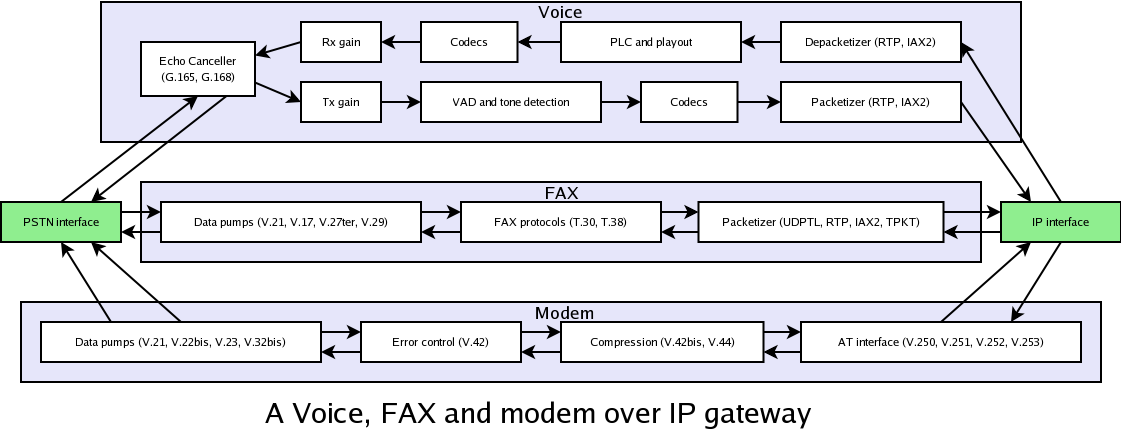
-
2024-06-16 at 3:33 PM UTCFaxing over IP networks
FAXing over VoIP networks
Executive summary
FAXing over VoIP networks doesn't work. You can sometimes arrange things so a fairly high percentage of FAXes get through OK. You can occassionally create setups that work 100% of the time. These are rare and unrepeatable setups. You need to use a proper FAX over IP protocol, such as T.38, to achieve consistent reliable FAXing across IP networks.
For the skeptical
Don't believe FAXing over VoIP protocols won't work? Heard that things will work OK if you use the G.711 u-law or A-law codec? Read on if you want to see why things are much more complex, and troublesome, than that.
Trying to live with FAXing over VoIP networks
Sending FAXes over VoIP networks usually fails. It is human nature to look for simple reasons for that, and simple cures. In reality, there are a number of reasons, and no certain universal cures. VoIP networks are designed to do a good job with speech. Carrying any sound other than a single voice speaking is not generally a system requirement. It shouldn't be too surprising if it works rather poorly.
During development work I have started finding some nasty behaviour in real world products, which I have started to document here.
You cannot get a quart into a pint point
The commonest problem with sending a FAX over VoIP networks is the easiest to deal with. A low bit rate voice codec is unable to carry a fast modem signal without severe distortion. Would you really expect an 8kbps G.729 codec to convey a 9.6kbps FAX modem signal correctly? If you would, you probably also believe in perpetual motion. I might even be able to offer you a good deal if you would like to buy London Bridge :-) The only common codecs capable of adequately preserving FAX modem signals up to 14,400bps (V.17) are u-law and A-law. Up to 9600bps (V.29) a fully implemented G.726 codec will also work. However not all codecs claiming to be G.726 fully implement the spec. A few shortcuts can save considerable compute power, and only a few people need the spec. to be fully implemented. Your mileage may vary. The G.726 codec was, however, specifically designed to be able to carry medium speed modems, such as the V.29 modem used for FAX.
Recently, FAX machines supporting 33,600bps (V.34bis) have become popular. This rate is unlikely to work with any reliability across any VoIP connection, even when an A-law or u-law codec is used. The codecs will maintain the required signal quality, but the delay across the VoIP channel, even if it is a stable delay, will prevent the echo cancelers in most modems from training well enough. The slower FAX modems - V.27ter, V.29 and V.17 - do not use echo cancellation, so the problem does not exist there.
Lower bit rate codecs have zero chance of working for any standard FAX image modem. Many will convey the 300bps (V.21) FAX control messages OK. They will not convey the fast modem signals, used for the actual image data.
Modems don't like relativity
In the PSTN world, the network provides a constant delay for any particular call. The speed at which data enters the network is always the same as the speed at which it leaves. The end to end delay does not jitter, or make step changes in anything but exceptional circumstances (e.g. on automatic fail-over, if a fibre link fails). Modems require this. In an IP network jitter it a fact of life. It can be kept to a modest level, through the use of the QoS (quality of service) features available in a lot of IP equipment, but only if you control the network end-to-end. If the call passes across the open Internet there is no QoS control. It is hard to see a business model that would ever encourage QoS to be introduced across the open Internet. So, in the long term the timing of a voice signal entering a VoIP network is the same as the timing as it leaves, but in the short term they can be very different.
If a VoIP network works only across a LAN or a QoS managed WAN link, there might be a near guarantee of zero packet loss, and fairly low jitter. Many people then assume the jitter buffer at the receiver will smooth out the modest jitter, and the received signal will perfectly match the transmitted one. They are often right, but there is no guarantee. There are many designs of jitter buffer. Most modern ones dynamically adapt the length of the buffer in some way, although many different algorithms are used. If the jitter is low, and dynamic jitter buffering is switched off, things may work well. If it cannot be switched off, the behaviour of dynamic buffering will generally upset a modem signal. Various algorithms will:
Guarantee some packet loss, by tuning the buffering until a small percentage of packets are declared late, and dropped. Dropping packets is actually built into these algorithms, and the results can be pretty good for voice. Trading a small number of dropped packets for somewhat less latency is a reasonable trade-off.
Adjust periods of silence in whole packet steps (typically 20ms). Certain silence periods in a FAX signal are specified as 75+-20ms. 20ms jumps can push them out of spec.
Continuously adjust the timing of non-silent periods, using overlap and add techniques. This is the state of the art in jitter buffering for voice, but a complete disaster for a modem.
Perversely, the more basic equipment is likely to work well, and the newer more sophisticated designs are likely to be troublesome.
Modems don't like silence suppression
Depending on its implementation in particular equipment, silence suppression can destroy a FAX call. If silence suppression is enabled, a voice detector continuously monitors the call, looking for the presence of a real voice. Some of these are designed to focus purely on voice, and tend to reject other kinds of sound - e.g. modem tones. They may, therefore, not switch the audio path on and off cleanly when the modem signal starts and stops. Even if they do switch cleanly, the suppression algorithms usually modify the audio around the switching points.
During silent periods, comfort noise is usually introduced, to simulate the background noise you normally hear in a conversation. This might mean a period which should be silent, is actually significantly noisy. The receiving modem might not see a good enough "silence" for its signal detector to correctly declare the boundaries of the modem signal.
Modems like a complete conversation
Modems need a continuous audio path. If there is packet loss the consequences are severe, but the actual effect depends a lot on the equipment in use. Lets say a 20ms packet of audio is lost in the middle of a page of FAX. Obviously this is going to loose a bit of the image, but will it affect just a small stripe, or the rest of the page? If the receiving end emits 20ms of silence, the receiving modem will probably declare the end of the page. If the receiving end emits 20ms of some fill in sound, the receiving modem might be able to ride over the gap, depending on its design. If more or less than 20ms of some fill in sound is emitted, the remainder of the page will definitely not be received correctly. The receiving modem will not tolerate a jump in timing of that sort.
The bottom line
FAX, and other modem applications, operating over VoIP channels are quirky, and unreliable. This will not get better over time. It will get worse. In general, the more sophisticated the equipment gets in trying to make speech work smoothly, the worse it behaves for modems. In the near term (i.e. until all data applications are native IP applications) store and forward protocols, and protocols tailored to reasonably conveying modem data across an IP channel are the only way to achieve consistent results.
FAX over IP (FoIP) specifications
Most current FAX machines lack an RJ-45 connector and a TCP/IP protocol stack. Few of even the latest models will connect directly to the Internet, even though the protocols for doing so have been standardised for several years. Only some quite high end machines seem to offer this. This means in a world increasingly moving to VoIP for telephony, support is needed for using conventional FAX machines over IP channels until most of those machines are consigned to the scrap-heap.
Store and forward FoIP (T.37)
The T.37 specification defines a standard method for store and forward delivery of FAXes through an IP network. It is simple, elegant, and reliable. Its only real drawback is that it is not real time. In reality this is not much of a drawback, but psychologically it is. Real time FAX gives the illusion that if your FAX machine says the FAX got through, it is now in the recipient's hands. Of course, this is completely bogus. It may be sitting in some store and forward unit (maybe the target FAX machine's buffer memory, or a unified message service) which you are unaware of. It may be sitting in a waste bin, mistaken for junk FAX. Of course, any sensible user knows this. It doesn't stop many taking an irrational attitude to the subject, though. Some people think a FAX machine report might have some legal standing as an indication a document were sent. It might even be true. Telex logs used to be accepted by courts, and they were trivial to forge.
The only real problem store and forward brings is the two endpoints are not able to negotiate their capabilities. FAXing is limited by the capabilities of the store and forward system. If you want to send a colour FAX between known colour FAX machines, and the store and forward system doesn't understand colour FAXes, there will be some surprise and disappointment when a monochrome FAX appears at the far end. Of course, improving the capabilities of the gateways, to more completely implement the current version of the FAX spec. can solve this.
T.37 defines a procedure for receiving a FAX at a gateway; making an e-mail message, containing the FAX as an attachment; sending it to a remote gateway; and dialing out and delivering it from the remote gateway to the destination machine. It might optionally be delivered as an e-mail with a FAX attachment directly to the recipient's e-mail box. Also, FAXes might be sent directly to the store and forward system from a sender's e-mail box, for delivery to a dialed FAX number.
T.37 is a very simple specification. It doesn't need to say very much. It builds upon well proven, widely deployed protocols - SMTP, MIME, etc. - and just defines a few details needed to bring them all together for the FAX application. This means it can be very simple to implement in any system which already contains most of the building blocks. T.37 is good. T.37 is wholesome. T.37 is the sane way to handle FAX at this time.
Real time FoIP (T.38)
Only one standard has been developed for real time FAX over IP - T.38. Before discussing what T.38 is like, it is important to note a few things about its current status in the real world. A lot of ATA boxes, and other gateway equipment, still do not support T.38. A lot which say they support it actually just have it in the pipeline (e.g. Sipura 2100). Very few T.38 implementations currently support 33,600bps (V.34bis) FAX, although recently low cost all in one printer/scanner/FAX machines supporting V.34 FAX have become fairly common. A lot have very buggy implementations - I have used a T.38 ATA box recently that simply locks up the moment it hears a FAX tone. If you think you know how T.38 behaves, you might just be familiar with how buggy versions behave.
So, what is T.38?
T.38 is the real-time FAX over IP protocol. This means it is designed to work like traditional FAXing. You call another FAX machine, and send the FAX as you wait. Either FAX machine could be a traditional FAX machine connected to the PSTN, an ATA box, or similar; it could be a FAX machine with an RJ-45 connector plugged straight into an IP network; it could be a computer pretending to be a FAX machine.
There are some issues in trying to do FoIP well with traditional FAX machines. Recent versions of the core FAX protocol - T.30 - have introduced flags and features to allow newer FAX machines to be Internet aware FAX devices. These tie in to the T.38 spec. A few makers now say their FAX machines are "Internet Aware" or "Internet Capable". This might mean the machines can connect directly to an IP network. It usually just means the machines are aware of the existance and qualities of T.38.
What does T.38 look like?
The original version of the T.38 spec. defined two methods for transmission across an IP network - one based on UDP and one based on TCP. At that time RTP was the emerging protocol for streaming media across IP networks. Instead of using that, T.38 defined its own method of packaging data within UDP packets, called UDPTL. This has now been accepted as a mistake, and an RTP based form of the protocol has been defined. Currently, this just makes more work for implementors. The only method in widespread use is the non-RTP method, so that has to be implemented. There is no choice. For the future, the RTP form has to be implemented too. AHHHH!
The T.38 spec. says some odd things about when the UDP form is more suitable and when the TCP form is more suitable. I would say the TCP form should be used between two IP devices. When one of the machines is connected to an analogue phone line, the UDP form probably has to be used for its nearer real-time streaming qualities. UDP is, however, an unreliable protocol, and that compromises the benefits of T.38 over trying to use FAX over VoIP.
T.38 is a very loose specification. Most good modern specifications try to really tie down what should happen. T.38 allows a huge spread of implementation decisions.
In what ways does T.38 outperform FAX over VoIP?
If the TCP form of T.38 is used, it is very robust. Used between Internet aware FAX machines, it basically solves all the problems of using VoIP for FAX.
If one of the UDP forms of T.38 is used, it is common for each packet to contain a copy of the main data in the previous packet. This is an option, but most implementations seem to support it. This forward error correction scheme makes T.38 far more tolerate of dropped packets than using VoIP. It requires two successive lost packets to actually loose any data. The overheads in T.38 are so big, the extra data sent in each packet is hardly noticable. If two successive packets are lost, T.38 will still have trouble. However, if that is a common occurance, the network is probably quite bad, and VoIP performance will be poor.
Loosing a packet in a T.38 stream does not cause the modems to loose sync. This means two successive lost packets should only corrupt a section of an image. If the optional FAX error correction (ECM) mode is used, there is a good chance that with a retry or two, a perfect image will be transferred. Not ideal, but functional.
Much of the robustness of T.38 comes not from what the spec. says, but from the potential it offers for smart implementation. The trick is to work out the smartest implementation, which will not cause trouble with the many buggy implementations of T.30 which exist in commercial FAX products.
The T.30 spec. allows transmission of a page to be paused just before the end of any row of pixels. This is used as a method of flow control, by FAX machines with slow paper handling. It can also be used by a T.38 implementation, to wait for more data when a packet is delayed or lost. This means a T.38 gateway can start sending a page as soon as it gets some data, without performing any jitter buffering. When there is little jitter, transmission delay is minimised. When jitter is bad, things will be delayed only as much as necessary. If packets are lost, and FEC is in use, the outgoing gateway can simply wait a while, to try to reconstruct the stream from the redundant information available when further packets arrive. If the required data is irretrievably lost, due to a burst of lost packets, transmission can continue with only the minimum possible page corruption.
HDLC transmission, used for the FAX control messages, offers no similar way to precisely control flow. However, it is possible to achieve pretty good results. The HDLC protocol only supports flow control between HDLC frames. The full HDLC protocol allows frames to be aborted midway, and restarted. However, the protocol as definition in the T.30 spec. doesn't include the abort feature. If we wait until we have received the whole of a long frame, before starting to pass it on, we could introduce substantial delay. However, this is not a big problem for T.30 FAX transmission. Most of the HDLC frames used in the T.30 spec. are quite short, especially the ones which occur between pages. Delaying until we receive all the data for one of these messages will not significantly extend the call. To avoid long delays for very long frames we can apply rules like: if a frame is no more than 30 bytes (1 second) long we wait for the whole frame to be received before passing it on; if the frame is longer we start passing it on with a 1 second delay.
What are the weaknesses of T.38?
T.38 cannot avoid the basic problem that it needs to deal with old FAX machines made before the idea of FoIP was ever considered. These machines expect certain timing constraints to be met. For these machines T.38 eliminates some problems, and reduces the scale of others. However, it is nothing like an FTP or HTTP transfer of an image in its ability to deal with poor network performance.
TO BE CONTINUED -
2024-06-16 at 3:35 PM UTC
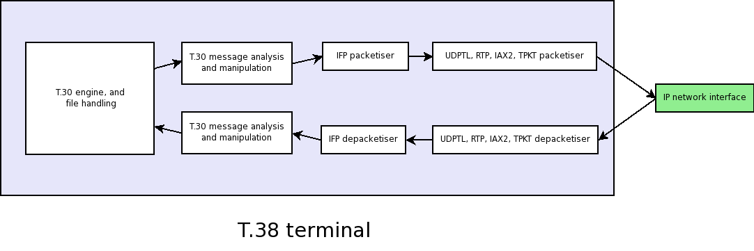
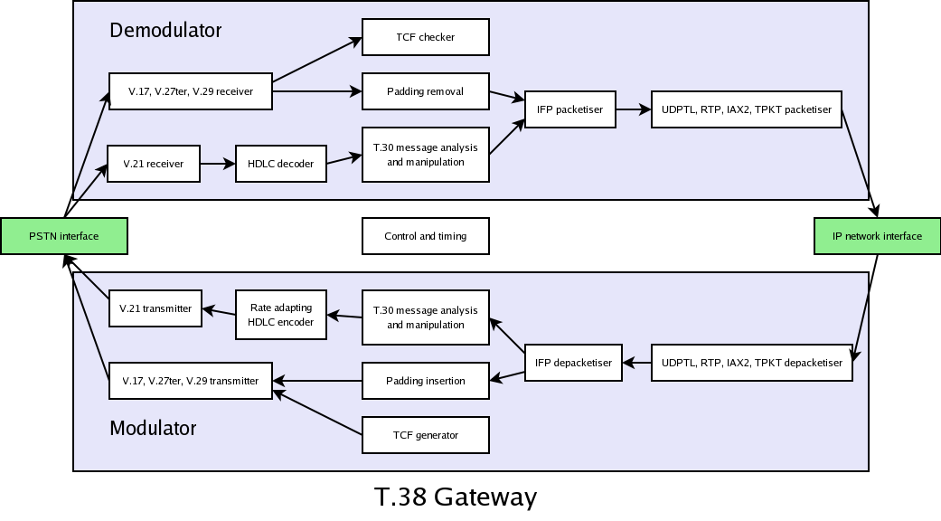
Chapter 2. The basics of a T.38 entity
The T.38 protocol may be used to build an Internet-aware FAX terminal, for direct connection to the Internet. It may also be used to build gateways. A T.38 FAX gateway might be a gateway between the PSTN and the Internet. It might just be an a ATA box acting as a gateway between a directly connected traditional FAX machine and the Internet. The T.38 protocol merely defines what passes between two T.38 entities. Creating a robust entity, able to tolerate the widest possible variation in network delays, jitter and packet loss, requires considerably more than just implementing what is contained in the T.38 spec. Also, the protocol definition is somewhat loose, resulting is considerable variability in the way the protocol is implemented. Considerable flexibility is required in a T.38 entity's design, to tolerate these variations.
T.38 currently works over one of the following transports:
TCP, with TPKT message framing - the use of TPKT was originally specified in a vague way, and implementations without TPKT framing apparently exist.
UDPTL - A UDP based protocol used nowhere else. This is the most common transport for T.38.
RTP - Added quite late to the T.38 specification, and still not widely supported.
TCP is the ideal way to communicate between two entities on an IP network, which do not have real-time constraints. The entities can talk as fast as they and the medium between them permit, with full error control. Internet-aware FAX devices would, therefore, usually use TCP as the transport for T.38. Gateways have only limited control of the timing of the FAX data passing through them. They have to operate in real-time, at a rate outside their control. Gateways, therefore, usually use UDPTL. The RTP option was only added to the T.38 specification in 2004, and is not yet widely supported. Over time it may become the preferred replacement for UDPTL, since most entities handle more than just FAX, and need to implement RTP anyway.
A TCP stream is fully corrected by the TCP protocol itself. However, in the UDPTL or RTP modes of operation, T.38 is subject to possible packet loss. A high level of missing data would defeat the protocol, so some measure of FEC (forward error correction) must be used. The UDPTL specification defines two optional forms of FEC. Both consist of adding information from previous packets to new packets. In one form this repeated data is send as a direct copy of the original. In the other it is sent as parity information, which requires encoding and decoding. The specifications for RTP include definitions of suitable FEC and redundancy protocols (RFC2198 and RFC2733). The T.38 specification says these should be used for T.38 over RTP.
Interestingly, even the latest revision of the T.38 specification does not provide properly for security in FAX transmission. SRTP is a standard way to achieve secure multi-media communication, and can be applied to T.38 over RTP without any specific wording on the subject in the T.38 specification. UDPTL might be seen as obsolete in the long term, and not worthy of enhancements to encrypt the data. However, no secure option for T.38 over TCP is defined. TPKT could be sent over TLS/TCP. TLS also has message framing features which would allow IFP packets to be sent directly over a TLS protected connection. However, there is no specified way to do this.
Although redundant information in future packets is an important part of a solid T.38 implementation, it is not a complete solution to problem of lost packets. Sometimes the next packet occurs after a considerable delay (e.g. when allowing time for a fast modem to train). If a "start training" message is only received through the redundant information in a following packet, it usually arrives too late to be useful (at least for a gateway). Most T.38 implementations now follow a practice of sending several exact copies of key packets - generally the ones which start or end the stages of the T.30 protocol. Typically up to 4 identical copies of these packets are sent down the wire. The may be sent in a burst, as fast as possible, or they may be spaced in time by 10ms or 20ms. IP network congestion, and the resulting packet loss, can be very bursty. If all copies are sent together, they might all be lost. Even a small amount of spreading in time may significantly increase the likelihood of at least one copy reaching its destination. The price is some delay in delivery of the message, which might be problematic. Multiple copies of these packets add little to the overall volume of data transmitted, as only a small percentage of packets fall in this "key packet" category. Some T.38 implementations follow a less effective practice of sending multiple key packets, which have separate sequence numbers and are separately bundled with redundant information for transmission. They may also be spaced in time. Although this seems a less effective strategy, a T.38 entity must expect to receive packets streams of this kind, and tolerate them.
Between the high priority key packets, and the low priority packets for the image data (the loss of which might just cause a streak on an image, or be corrected by ECM FAXing), lies the V.21 HDLC control messages. Some T.38 implementations dynamically adjust the amount of redundant information in packets, so these control messages are repeated through several packets, but the large image data packets are repeated less, or not at all. Used with care, this dynamic redundancy strategy can nicely balance data volume and reliability.
A T.38 terminal has a lot more flexibility in how it can deal with problem data than a T.38 gateway. The terminal has no tight timing constraints governing how it behaves with regard to received data. It can wait a considerable period for delayed packets to arrive. The gateway is a man-in-the-middle, and must live with the timing constraints that imposes. This means a T.38 gateway has a rather more difficult design than a terminal. -
2024-06-16 at 3:37 PM UTCConventional dial-up modems.
Many people ask if they can use a dial-up modem as a telephony interface, and seem shocked when the generic answer is "no", blaming it on various conspiracy theories. The honest answer is genuinely "no" right now, although the full answer is a little more complex.
Dial up modems come in several forms, typically:
External modems, with a telephone socket on one side, and an RS232C port on the other.
Smart modems, with a telephone socket on one side, and a USB port on the other.
Smart modems, which are PCI/PCI-E/PCMCIA cards with a telephone socket on the back.
Dumb modems, with a telephone socket on one side, and a USB port on the other.
Dumb modems, which are PCI/PCI-E/PCMCIA cards a telephone socket on the back.
External modems are the classic modem design. The smart USB and PCI/PCI-E/PCMCIA modems are functionally very similar. On one side they whistle, and on the other they exchange bits of data with your computer. They are built to do this one job, and cannot reasonably be adapted to do anything else. Some of them have a limited voice ability, which a few modem makers added to provide voice mail functionality. They don't, however, offer the kind of full duplex, low-latency, voice features needed for most telephony.
The dumb USB and PCI/PCI-E/PCMCIA modems are more interesting from a general telephony point of view. Their hardware is functionally very similar to the FXO analogue telephony cards available from people like Digium and Sangoma. Everything that makes them behave as a modem is in host software, which could be replaced by general purpose telephony software. Most of these devices run at 9600 samples/second when used in modem applications. However, most can be reprogrammed to sample at 8000 samples/second, which is more compatible with general purpose telephony applications.
Today, the only dumb modem devices with a well supported telephony driver are those using the obsolete Intel 536 chip. That driver exists because Digium used to sell a single port FXO card which used this device. However, most of the popular dumb modem devices now have Linux support. The modem code is normally supplied as a binary object. However, the card interface code is normally supplied as source code. It is easy to see how this code might be easily reworked to form a general purpose telephony device driver. All that is lacking is people with the time, skills, and motivation to do that work. -
2024-06-16 at 3:53 PM UTCYou can "shotgun" two US robotics 33.6 modems and run them in tandem.
-
2024-06-16 at 3:58 PM UTCWhere would American culture be without such musical sensations as NBA Youngboy and Puuh Sheisty ?
-
2024-06-16 at 4:32 PM UTCChingy
-
2024-06-17 at 3:44 AM UTC
$$$$$$$$$$$$$$$$$$$$$$$$$$$$$$$$$$$$$$$$$$$$$$$$$$$$$$$$$$$$$$$$$$$$$$$$$$$$$$$
$$$$$$$$$$$$$$$$$$$$$$$$$$$$$$$$$$$$$$$$$$$$$$$$$$$$$$$$$$$$$$$$$$$$$$$$$$$$$$$
$$$$$$$$$$$$$$$$$$$$$$$$$$$$$$$$$S7~~~~~|~~~YS$$$$$$$$$$$$$$$$$$$$$$$$$$$$$$$$$
$$$$$$$$$$$$$$$$$$$$$$$$$$$$S"          |         """S$$$$$$$$$$$$$$$$$$$$$$$$$
$$$$$$$$$$$$$$$$$$$$$$$$S"              |              `$$$$$$$$$$$$$$$$$$$$$$$
$$$$$$$$$$$$$$$$$$$$$S"                 |               _/`S$$$$$$$$$$$$$$$$$$$
$$$$$$$$$$$$$$$$$$$"                    |              /      "$$$$$$$$$$$$$$$$
$$$$$$$$$$$$$$$$$"                      |             /__       `$$$$$$$$$$$$$$
$$$$$$$$$$$$$$$$'            ___        |  _          _/         `$$$$$$$$$$$$$
$$$$$$$$$$$$$$'    _          ---       | (c)_  _    /             `$$$$$$$$$$$
$$$$$$$$$$$$" ,--.(c)         .-'`)     |,'_ _`(c)  /___            `$$$$$$$$$$
$$$$$$$$$$$$(c)     `.      =( (  ;     | (.).) )     /               $$$$$$$$$
$$$$$$$$$$$' :  (.).) ;     '"";  ;   .'|       ;   _/__              $$$$$$$$$
$$$$$$$$$$$  :  .   QQ ;       ;   ;.-`.|( QQ ) ;  /                   $$$$$$$$
$$$$$$$$$$'.'  `.  (.j.)`.    ;         | VVVV  `,/___                 $$$$$$$$
$$$$$$$$$$       `-.      `. ;          | ._.    `.  /                 $$$$$$$$
$$$$$$$$$$                  `:          |         `./______/\/\/\/\____$$$$$$$$
$$$$$$$$$$------------------------------+------------------------------$$$$$$$$
$$$$$$$$$$               :   `.;        | =(~~~~~   `,      |   |      $$$$$$$$
$$$$$$$$$$               :    ;;        |  =(_______,'      |   |      $$$$$$$$
$$$$$$$$$$.              `.  .'         |        `,         |   |     .$$$$$$$$
$$$$$$$$$$$               ;  ;:         |          `,       |   |    .S$$$$$$$$
$$$$$$$$$$$.               VV :         |           ;       |   |    .$$$$$$$$$
$$$$$$$$$$$$                  :         |           ;       |   |   .$$$$$$$$$$
$$$$$$$$$$$$$                 `,        |           `.     /    |   .$$$$$$$$$$
$$$$$$$$$$$$$.                  ;       |            ;    /     | .sS$$$$$$$$$$
$$$$$$$$$$$$$$.                 :       |           ;    /      | .$$$$$$$$$$$$
$$$$$$$$$$$$$$$$.             ,'        |           ;    ~~~~~~~.s$$$$$$$$$$$$$
$$$$$$$$$$$$$$$$Ss        ,','          |         ,'           .s$$$$$$$$$$$$$$
$$$$$$$$$$$$$$$$$$$Ss.  ,' ,L_   `.     |     ,'  L__        .s$$$$$$$$$$$$$$$$
$$$$$$$$$$$$$$$$$$$$$$Ss. ' ___)---`----|----'_____)))-    .sS$$$$$$$$$$$$$$$$$
$$$$$$$$$$$$$$$$$$$$$$$$$$$s )-         |              .sSSSSSSSSSSSSSSSSSSSSSS
$$$$$$$$$$$$$$$$$$$$$$$$$$$$$Ss-.       |          .sS$$$$$$$$$$$$$$$$$$$$$$$$$
$$$$$$$$$$$$$$$$$$$$$$$$$$$$$$$$$$$$$$$$$$$$$$$$$$$$$$$$$$$$$$$$$$$$$$$$$$$$$$$
$$$$$$$$$$$$$$$$$$$$$$$$$$$$$$$$$$$$$$$$$$$$$$$$$$$$$$$$$$$$$$$$$$$$$$ dp $$$$$
$$$$$$$$$$$$$$$$$$$$$$$$$$$$$$$$$$$$$$$$$$$$$$$$$$$$$$$$$$$$$$$$$$$$$$$$$$$$$$$ -
2024-06-17 at 4:03 AM UTC

-
2024-06-17 at 6:10 PM UTC[zn.hcl.reduction] [piperonal.from.pepper] [back]
Untersuchung über die Constitution des Piperins und seiner Spaltprodukte R. Fittig, W. Mielck, Universität Göttingen, 1869
piperonal from pepper 3base, Rhodium Archive, 2002
Extraction of Piperine from Piper nigrum (Black Pepper) by Hydrotropic Solubilization G. Raman, V. Gaikar, University of Mumbai, 2002
Heliotropin preparation method Patent CN102329297A, 2011
Extraction of piperine from Piper longum using ultrasound Rathod, 2014
Synthese von Piperinsaeure aus Piperin Ni2, illumina-chemie Forum, 2015
Black Pepper Extraction The Preston Impression, YouTube, 16.10.2021 [mp4]
Ozonolysis in Solvent/Water Mixtures: Direct Conversion of Alkenes to Aldehydes and Ketones C. Schiaffo, P. Dussault, University of Nebraska–Lincoln, 2008
An Improved Procedure for Alkene Ozonolysis C. Schiaffo, University of Nebraska–Lincoln, 2011
Alkene ozonolysis in the academic lab P. Dussault, University of Nebraska–Lincoln, 2016
Alkene ozonolysis T. Fisher, P. Dussault, University of Nebraska–Lincoln, 2017
Piperine Ozonolysis Attemp, psyhare, The Vespiary - Drug Synthesis & Extraction, 01.09.2019.
Household Ozone Disinfector as An Alternative Ozone Generator for Ozonolysis of Alkenes, S. Buntasana et. al., 2021
Synthesis and impurity profiling of MDMA prepared from commonly available starting materials, R. Gallagher et al., University of Technology Sydney, 2007 [pdf]
The synthesis and characterisation of MDMA derived from a catalytic oxidation of material isolated from black pepper, C. Plummer et. al, Melbourne, 2016 [pdf]
Piperonal Synthesis, Kimia Organik IPB, YouTube, 2020
Kimia Organik IPB, YouTube, 10.09.2020 Kimia Organik IPB, YouTube, 16.09.2020 Kimia Organik IPB, YouTube, 25.09.2020 Kimia Organik IPB, YouTube, 30.09.2020 Kimia Organik IPB, YouTube, 07.10.2020 Kimia Organik IPB, YouTube, 15.10.2020
-
2024-06-18 at 6:05 AM UTC
-
2024-06-18 at 4:33 PM UTCгра на гроші з виводом
-
2024-06-18 at 9:47 PM UTC


