

User Controls
Anyone here experienced with Arduino, or at least electronic circuitry more generally?
-
2019-04-19 at 5:49 AM UTC
Originally posted by gadzooks I have a multimeter lying around… I haven't used it in at least a year, but I imagine it still works. I can easily get another one if that's not the case. They aren't that expensive.
But, really good suggestion though! I was thinking I was going to have to test the wires in some convoluted trial-and-error kind of way, directly into the Arduino. But a multimeter can tell me a lot about the signal that each wire is transmitting.
i dont mean to insult you but if it never occured to you to deploy meters, be it of multiple functions or single functioned meters when it comes to testing IOs,
then i think you shouldnt be messing with electrical stuffs. its not so much as lack of knowledge but more of a lack of logical thoughts.
idk. -
2019-04-19 at 5:52 AM UTC
Originally posted by vindicktive vinny i dont mean to insult you but if it never occured to you to deploy meters, be it of multiple functions or single functioned meters when it comes to testing IOs,
then i think you shouldnt be messing with electrical stuffs. its not so much as lack of knowledge but more of a lack of logical thoughts.
idk.
Everyone has to start somewhere.
You don't think I've heard some absolutely ridiculous programming or computer science questions before?
I prefer to encourage them learning more, rather than quitting altogether.
Of course, messing around with electricity has deeper potential repercussions... Electrical shock can be fatal.
But I can't imagine testing =<12 volt wires with a multimeter being all that fatal.The following users say it would be alright if the author of this post didn't die in a fire! -
2019-04-19 at 5:57 AM UTC
Originally posted by aldra 3. Regardless it looks like that particular intercom uses a 12v EM lock, so to unlock the door you need to interrupt the 12v line. You'll need to wire in a relay to do this. An arduino relay board/shield is a cheap and easy way to do it and will work fine with the raspi.
i always think this kind of locking mechanism is shitty and designed by retards or it's meant to be used for low security functions.
proper locks should always be always locked, interupt to open, and a manual unlocking mechanism for when power fails,The following users say it would be alright if the author of this post didn't die in a fire! -
2019-04-19 at 6 AM UTC
Originally posted by gadzooks Everyone has to start somewhere.
You don't think I've heard some absolutely ridiculous programming or computer science questions before?
I prefer to encourage them learning more, rather than quitting altogether.
Of course, messing around with electricity has deeper potential repercussions… Electrical shock can be fatal.
But I can't imagine testing =<12 volt wires with a multimeter being all that fatal.
its to prevent you from forming it into a habit. you have a habit of plug frist, ask questions later.
remember that hdd episode ? -
2019-04-19 at 7:09 PM UTC
Originally posted by vindicktive vinny its to prevent you from forming it into a habit. you have a habit of plug frist, ask questions later.
remember that hdd episode ?
That was the simplest mistake that literally anyone can make.
You know that a common error made by surgeons is removing the wrong kidney during a transplant/donation?
Literally everybody makes mistakes. Mine was relatively trivial. -
2019-04-20 at 5:48 PM UTC
-
2019-04-21 at 4:31 AM UTCNeed schematic for Airphone VC-K to know it's pinout.
-
2019-04-21 at 12:33 PM UTCOMG...
I nearly blew my load when I found that. -
2019-04-21 at 12:35 PM UTC
-
2019-04-21 at 12:41 PM UTCActually, I may have spoken too soon... The context for that is an entry hack device...
https://talesofatech.com/2017/05/remote-building-entry-hack-step-2-the-beta-build/#more-1751
Still super educational for my purposes though. -
2019-04-21 at 12:42 PM UTCGad,
It seems like you are enjoying this project and are learning a lot. I think that’s cool you decided to DIY, I’d probably pay someone to do it.The following users say it would be alright if the author of this post didn't die in a fire! -
2019-04-21 at 2:20 PM UTC
Originally posted by Technologist Gad,
It seems like you are enjoying this project and are learning a lot. I think that’s cool you decided to DIY, I’d probably pay someone to do it.
Yeah. I love learning new things that I have little to no understanding of.
The end product (a WiFi connected Intercom system) is only one of two major goals here.
The educational value may even be the more desirable of the two. -
2019-04-21 at 2:38 PM UTC
Originally posted by billfred Need schematic for Airphone VC-K to know it's pinout.
http://www.intercomsrus.com/handset%20pdf/Aiphone%20VC-K%20door%20entry%20handset%20data%20sheet.pdf
it's got 5 terminals lol, would've been easy enough to test them with a multimeter
Originally posted by gadzooks Actually, I may have spoken too soon… The context for that is an entry hack device…
https://talesofatech.com/2017/05/remote-building-entry-hack-step-2-the-beta-build/#more-1751
Still super educational for my purposes though.
the wiring will mostly be the same for what you want to do; their goal is just to intercept the signal received when someone hits the buzzer (12v on the buzzer line) and immediately trigger the relay to release the door. you won't need to worry about wiring anything on the buzzer line, rather you'll want to work with the audio line.
I'll draw up a diagram on how you'll probably want to wire everything to your raspberry piThe following users say it would be alright if the author of this post didn't die in a fire! -
2019-04-23 at 11:17 AM UTCReally interesting project Gad, looking forward to seeing Aldra's schematics. Personally i think i would just go mostly low tech on this one and set most of the stuff up with either relays and/or transistors depending on the voltage. I'm not much of a hardware guy, but i'd probably rig it so that when the buzzer goes it triggers a relay or transistor to supply a current to a simple receiver in a switchboard like setup, depending on what the receiver is designated for and whether the signal is on or off you could probably trigger a script to programmatically follow up with the steps you want happen next, if you are able to monitor what is happening on the switchboard. Like send some data over wifi to your phone where you have an app that can send data back that controls the rPi driving the switchboard or whatever.The following users say it would be alright if the author of this post didn't die in a fire!
-
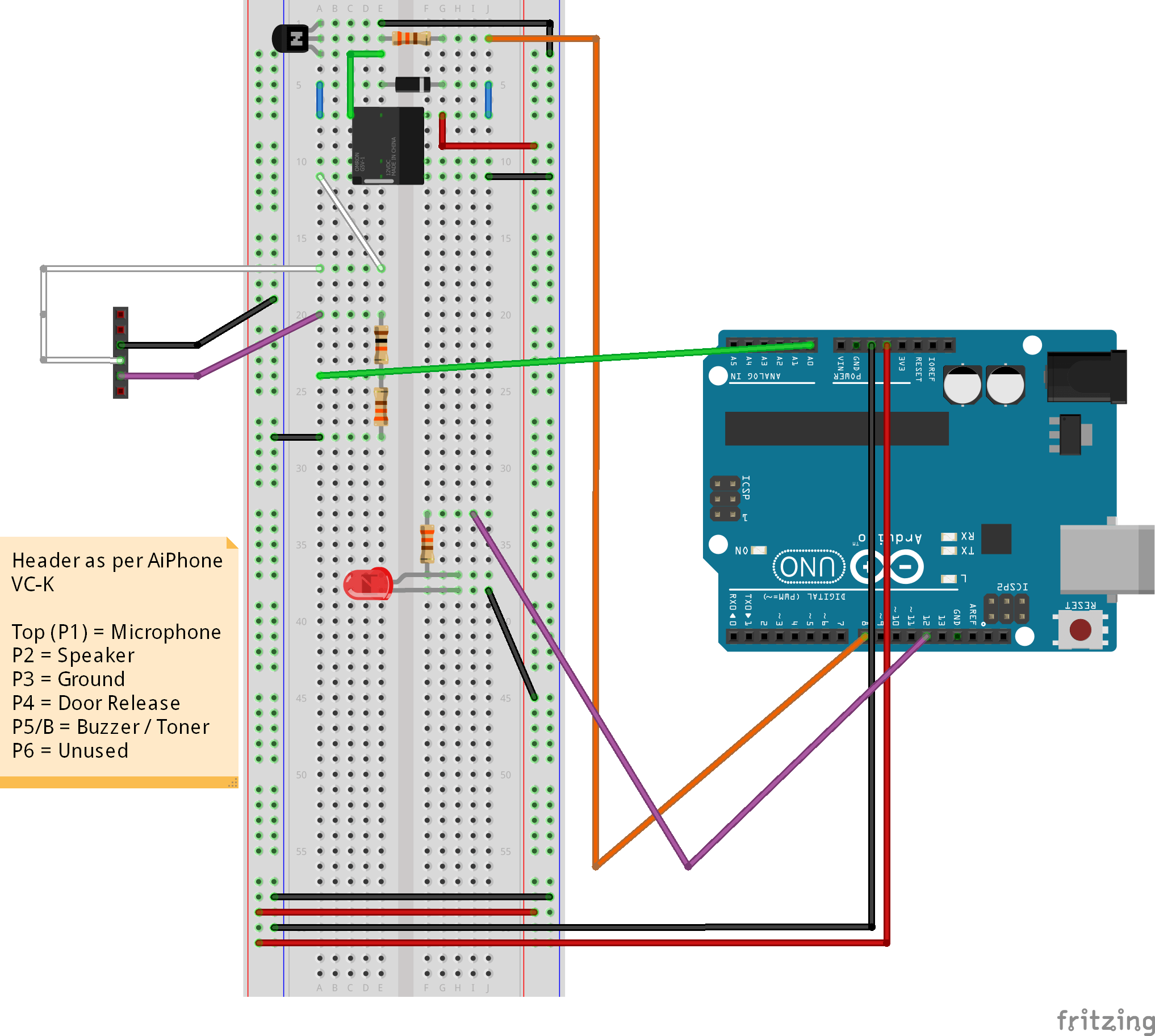
2019-04-23 at 4:13 PM UTCOK so I tried to use FRITZING but I shit the bed and just did a shitty drawing in gimp instead.
FIRST: Use a multimeter on the DOOR_RELEASE (4) line and check the voltage when you hit the button to release the lock. I'm assuming the line is a constant 12v that is interrupted/grounded (voltage drops to 0) when you hit the release button.
Basically my idea is:
1. Get a USB sound card, wire the SPEECH_IN/SPEECH_OUT (2/3) pins to mono plugs, plug them into the sound card to send and receive audio. Test it to make sure levels are OK before you try to access the audio programmatically.
2. Get an arduino 5/12v relay board (you can just use a 5v relay but this is neater). Wire the DOOR_RELEASE (4) pin to COM(MON). Wire GROUND (3) to NO (Normally Open). Basically you ONLY want to ground the door release wire when the relay is activated - this is what triggers the door to unlock. You can potentially do it the other way around, put ground to NC (Normally Closed) but this would mean that the relay has to be activated for the door to lock, so if your device were to lose power for whatever reason the door would be permanently locked open.
3. On the relay board, wire the GROUND and VCC pins to the correct GPIOs on your Raspberry Pi - reference. You can wire the IN pin (if you use a relay board with more than one relay there will be an IN pin that corresponds to each relay - in the image it's a 2-relay board but you can go with 1; I only used it because it was the best image I could find) to any free GPIO you want, I connected it to GPIO2 for convenience.
NOTE: The relay requires 5v to operate; depending on the power supply you're using you may not be able to power it directly from the raspberry pi power rail. If this is the case attach a 5v battery or other appropriate power supply to the VCC/GND pins on the relay board.
4. You should now be set up to code. Try to play and record sounds on the usb sound card to test that. To test the door locking mechanism, set GPIO2 (or whatever pin you have the relay control attached to) to HIGH to unlock and LOW to lock (1 and 0 digital signals). I can write some example code in perl if you want but I suspect you won't have much trouble with that part.
Example cheap parts:
Sound Card:
https://www.amazon.com/Sabrent-External-Adapter-Windows-AU-MMSA/dp/B00IRVQ0F8/
Mono Connectors (stereo is fine, just wire the line to both L and R):
https://www.amazon.com/Ancable-10-Pack-3-5mm-Solder-Connector/dp/B077XSZ5BK/
Single Relay Board (can use multiple, don't really need to though):
https://www.amazon.com/Tolako-Arduino-Indicator-Channel-Official/dp/B00VRUAHLE
Originally posted by Sophie Really interesting project Gad, looking forward to seeing Aldra's schematics. Personally i think i would just go mostly low tech on this one and set most of the stuff up with either relays and/or transistors depending on the voltage. I'm not much of a hardware guy, but i'd probably rig it so that when the buzzer goes it triggers a relay or transistor to supply a current to a simple receiver in a switchboard like setup
that's almost exactly what the project in his link does lol -
2019-04-23 at 4:58 PM UTC
Originally posted by aldra 2. Get an arduino 5/12v relay board (you can just use a 5v relay but this is neater). Wire the DOOR_RELEASE (4) pin to COM(MON). Wire GROUND (3) to NO (Normally Open). Basically you ONLY want to ground the door release wire when the relay is activated - this is what triggers the door to unlock. You can potentially do it the other way around, put ground to NC (Normally Closed) but this would mean that the relay has to be activated for the door to lock, so if your device were to lose power for whatever reason the door would be permanently locked open.
i dont really understand this.
if the door is locked with an electromagnetic lock then wouldnt losing power would result in door being unlocked anyway ? -
2019-04-23 at 5:04 PM UTC
Originally posted by aldra Sound Card:
https://www.amazon.com/Sabrent-External-Adapter-Windows-AU-MMSA/dp/B00IRVQ0F8/
Buying that USB sound card ASAP. Luckily it ships to Canada, is only $10, and works with Linux. The only thing I'm a tad worried about is whether or not the RPi in particular can handle it. From what I gather it uses software for audio processing, and I've read some stuff online about RPi not being ideal for audio processing, and I know that in order to use GPIO, I have to use the Raspbian Linux Kernel specifically (from what I understand, at least).
Either way, $10 is nothing so I'll buy one of these and give it a shot.
Originally posted by aldra Mono Connectors (stereo is fine, just wire the line to both L and R):
https://www.amazon.com/Ancable-10-Pack-3-5mm-Solder-Connector/dp/B077XSZ5BK/
It never would have occured to me that these are even a thing they make...
And available in Canada.
Definitely buying a bunch of these.
Originally posted by aldra Single Relay Board (can use multiple, don't really need to though):
https://www.amazon.com/Tolako-Arduino-Indicator-Channel-Official/dp/B00VRUAHL
This particular relay board isn't available (at least on Amazon) to Canada.
BUT, I still have some more research to do on the relay switch element anyway, so that part can wait a few days. -
2019-04-23 at 5:05 PM UTCOverall, though, Aldra, fantastic diagram.
And, again, I really appreciate the research you've put into this.
I'm now 100% motivated to complete this project. -
2019-04-23 at 5:05 PM UTCAre the uninvited still coming around? Maybe youre doing all this for nothin...
-
2019-04-23 at 5:11 PM UTC
Originally posted by gadzooks This particular relay board isn't available (at least on Amazon) to Canada.
BUT, I still have some more research to do on the relay switch element anyway, so that part can wait a few days.
These two are available to ship to Canada:
https://www.amazon.ca/RoboJax-Relay-Module-Arduino-Triggered/dp/B07BL2JYKV/ref=pd_sbs_147_5/141-1137126-0094540?_encoding=UTF8&pd_rd_i=B07BL2JYKV&pd_rd_r=a4330354-65ea-11e9-b421-cdcde3290510&pd_rd_w=jhjjB&pd_rd_wg=DiwOq&pf_rd_p=5dcda75b-8643-4da3-9bb1-5c0233790500&pf_rd_r=Y9AWJ1B51B3G9DDC4BC7&psc=1&refRID=Y9AWJ1B51B3G9DDC4BC7
https://www.amazon.ca/dp/B073HX1DK2/ref=sspa_dk_detail_6?psc=1&pd_rd_i=B073HX1DK2&pd_rd_w=cT7nv&pf_rd_p=4b7c8c1c-293f-4b1e-a49a-8787dff31bcb&pd_rd_wg=l9CYg&pf_rd_r=HCMS9KRBPKNB147VWFFK&pd_rd_r=f113dee6-65e8-11e9-afd4-2da01f345a74
I imagine they are equivalent.


